


The world is going to hell in a hand basket. I just don’t care anymore.
— Unhappy person
We’ve all experienced this sort of pessimism, either first- or second-hand. It’s the hands-up, “I surrender,” “I’m going to focus on what I can control” feeling… and it’s not the kind of don’t-care pessimism that this article is about. Nor are we going to talk about the Centers for Disease Control. If that’s why you’re here, prepare to be disappointed.
Rather, we’re here to talk about resolving don’t-care states or Xs, in gate-level simulation. It’s an issue referred to as “pessimism,” although that may not mean what you think. Even the X states, in our context here, are better described as “don’t know” than “don’t care.”
As Real Intent describes the problem, synthesis can create one issue for simulation, and simulators may create a different one in an attempt to fix the first one. The problem applies largely to multiplexers whose select value isn’t yet known. These are expressed in RTL by if/then/else constructs. The “default” behavior is that, if the selector isn’t known, then the default branch – the “else” branch – is chosen, which may not be correct.
Apparently, as an example, Synopsys’s VCS simulator attempts to correct this, but the result can be X’s that aren’t really “don’t know” – at least for a human. You could analyze such a situation and realize that, in fact, the value of the signal can be known. Depending on how you approach the problem, it can be difficult for a computer to do that, however.
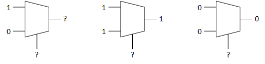
To be clear, there are definitely times when “don’t know” is appropriate. If a mux has a 1 on one input and a 0 on the other and the selector is unknown, then the output of the mux is definitely unknown. But what if the inputs to the mux are both 1 or both 0? Then the output of the mux no longer depends on the selector value, and the mux output value is definitively known. And yet this will be marked as an X – largely because the simulator is incapable of moving up the logic cone to figure the situation out.
As a result, many verification engineers can spend weeks sorting through the Xs to eliminate the ones that aren’t valid. And Real Intent says that those engineers have been lobbying for a tool to help with this. While they say that gate-level simulation isn’t going anywhere, it has been largely automated, meaning that there are fewer engineers digging in at that level even while all this manual work remains.
As regards characterizing the decisions as pessimistic, well, some might say that defaulting to the default branch of an if/then/else is pessimistic, but it’s not clear which branch would semantically be the “optimistic” or “pessimistic” branch – only the original designer would know that. But the resolution is pessimistic in the sense that, even when the output could theoretically be known, the tool can’t figure that out, and so it labels it X in an overabundance of caution.
Verix SimFix
Real Intent’s answer to this is their new SimFix program. It runs static analysis on the design, identifying situations where the simulator would think the answer is X, but, in fact, the answer can be known not to be X. The program is used before simulation where it generates a corrections file that can be referenced during simulation to pick the correct values when these situations occur.
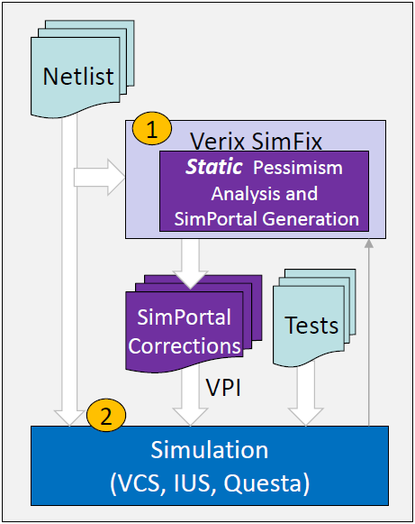
(Image courtesy Real Intent)
The analysis isn’t exhaustive; it’s “best effort.” Which means that there’s a chance that it won’t find everything on a given analysis run. Any Xs encountered in simulation after running SimFix will be logged, and the SimFix analysis can be repeated, supplementing the corrections file.
The analysis is independent of the simulation state at any time; it also appears to be independent of testbench. You can create your corrections file while running one testbench and then import it into other testbenches as well. Those other testbenches may unearth a few more pessimistic Xs, but, as a result, Real Intent guarantees that all cases can be caught over all testbenches.
Simulation performance isn’t significantly affected overall, they say. These Xs show up mostly during the initialization stage, where they might have at most a 10-20% impact. Once initialization is done, there are few remaining Xs floating around.
You can analyze individual modules, generating multiple corrections files. But the simulation being done here is assumed to be full-chip – this is not just a module-level solution.
That said, a thin layer is added to the simulator to monitor critical signals. And there could be a lot of those signals. But they trigger only on value change, which keeps the performance impact low. As to the corrections file, expressing it in Verilog or C wouldn’t scale well, so they have a patented format for the corrections; it’s a data file rather than a code file. It has no impact on the simulation compile time.
PhyCDC for Gate-Level CDC Analysis
Meanwhile, in a completely different corner of Verix, Real Intent has announced a gate-level CDC tool for fixing clock-domain-crossing issues that may have surfaced during synthesis. Most CDC work is done at the RTL level, but, in the process of creating the gate-level netlist, the synthesis engine may introduce logic that’s glitchy, or it may incorrectly optimize clock synchronizer logic in an attempt to lower power. And inserted test logic can also create new issues. CDC “sign-off” usually happens at the RTL level, but if new issues arise at the gate level, then that sign-off is no longer valid.
Note that this isn’t an “automatic fix” program. It’s a tool that helps to identify issues that might otherwise go unnoticed so that they can be fixed.
The original Verix CDC program saves information about the clock-domain crossings it encountered so that, at the gate level, PhyCDC can run an equivalence check to see which crossings might have been changed by synthesis. It also runs a comprehensive glitch analysis. Any issues encountered can be visualized through their iDebug tool.
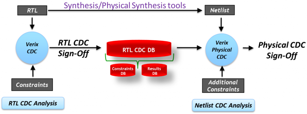
(Image courtesy Real Intent)
There’s always been a slight tension between high-abstraction design formats like RTL and implementation-level formats like the gate-level netlist. Equivalence checking was once done between them simply to prove that the synthesis step didn’t make a mistake – that the result was logically equivalent to the original.
In these two cases, it’s not so much about mistakes; it’s about artifacts intentionally introduced, but in a way that might negatively affect the design or, at the very least, cause a lot of work in proving that things are still OK. These tools are a productivity boost for folks trying to turn out correct, robust designs in less time.
More info:


What do you think of Real Intent’s gate-level X-pessimism and CDC solutions?
X-pessimism is an artificial problem caused by the bad/compact signal used by the original Verilog. Nowadays you can use nettypes in SystemVerilog and split out the components of the signal so that the uncertainty (X) is just tags saying you forgot to do things (like reset, power,…) and the logic value is separate and always a consistent 1 or 0.
All the CDC solutions are static-analysis, except this approach –
http://www.v-ms.com/ICCAD-2014.pdf
– which would also work with SV nettypes and UVM functional verification you do anyway (just different cell models in the DUT).
There are a lot of tools tackling artificial problems in EDA, I say just fix the root causes instead of doing workarounds, and life will be better for everyone.