


Just in case you are arriving late to the party, and you’ve missed my earlier columns, earlier this year I was introduced to an 11-year-old lad called Zeke who is on a mission to talk to the astronauts and cosmonauts orbiting the Earth in the International Space Station (ISS).
Zeke commenced this quest by getting his ham radio license when he was only 8 years old, and he’s now working on getting his homemade 10-foot helical antenna to track the ISS. In Part 1 of this mini-mega-series we met Zeke and his dad Eric and learned how this odyssey all began. Next, in Part 2 we saw how Zeke and Eric built the first incarnation of their 10-foot helical antenna and mounted it on their deck. Most recently, in Part 3, we discovered how Zeke used AWR Microwave Office from Cadence to design the motor control board that will be mounted in the rotor casings to control the antenna’s azimuth value (its rotational direction) and its elevation.
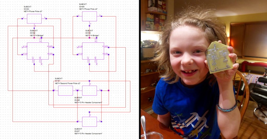
Designing and etching the “rocket” board (Source: KJ7NLL)
Also in Part 3, we discussed how the original helical antenna built by Zeke and Eric had only a single very high frequency (VHF) winding to talk to the ISS on the 2-meter (2m) band. Since the ISS also has an ultra-high frequency (UHF) repeater that allows other people to listen in on their conversations, Zeke and Eric used the Clarity 3D Solver from Cadence to perform 3D electromagnetic (EM) simulations to determine if adding a coaxial secondary 70cm UHF winding to their antenna would interfere with the primary 2m VHF winding.
In this column, we are going to turn our attention to the software side of things. Just for giggles and grins, let’s commence with the algorithm Zeke and Eric use to drive the motors in the rotors controlling the azimuth and elevation of the antenna.
They started with the simplest option, which was to control the motor in one rotor, activating a switch by hand and “eyeballing” the direction of the antenna. The next step was to incorporate a multi-turn potentiometer (pot) into the rotor, where the rotation of the rotor also drives the pot, and to use the resistance value of the pot to determine the direction of the antenna. They began by pointing the antenna as far as they wanted it to go in one direction and noting the resistance of the pot. Next, they pointed the antenna as far as they wanted it to go in the other direction and again noted the resistance of the pot. Then they created an Excel “cheat-sheet” that performed a linear interpolation of degrees and potentiometer values. Zeke just emailed me a photo of this cheat-sheet as shown below.
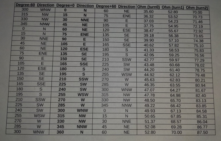
Creating an Excel “cheat-sheet” (Source: KJ7NLL)
Now, Zeke could use the switch to control the motor while observing the resistance value from the pot, employing his cheat-sheet to determine when the antenna was pointing in the right direction.
The next step was to use an EFR32MG21 microcontroller development board from Silicon Labs to take Zeke out of the loop. The idea here was for Zeke to be able to key in a desired angle, and for the microcontroller to monitor the value on the pot and drive Zeke’s motor control board to control the motor.
Unfortunately, Zeke and Eric ran into problems with their prototype model, which would first overshoot and then undershoot the desired position, eventually ending up “hunting” (oscillating around) the desired position. The problem was even more pronounced with the full-size helical antenna.
The issue was the control algorithm their microcontroller was using, which was what engineers would call an “On/Off” or “Bang-Bang” closed loop control system. In this case, the microcontroller determined the required direction and then drove the motor full on until the antenna reached the desired position. At this point, momentum and inertia caused the antenna to overshoot its target position, resulting in the microcontroller driving the motor in the opposite direction, and so it went. Even when the antenna came close to settling on its desired position, small amounts of random noise on the analog input signal from the pot caused the microcontroller to continuously apply corrections.
Let’s try an experiment. Hold your right arm out horizontally with your index finger pointing into the distance. Now, as fast as you can, bring your arm in and use that finger to touch the end of your nose. What many people don’t appreciate is the fact that the speed of their arm varies throughout the cycle. If you simply moved your arm as fast as you could, you would end up smacking yourself in the face, which is generally considered to be not a good thing to happen. To avoid this occurrence, you could move your arm very, very slowly, but then you would get bored waiting for your finger to arrive at its destination. The solution is to tell your arm to accelerate to high speed at the beginning of the motion, and then instruct it to decelerate as your finger approaches your nose.
All of this was new to both Zeke and Eric. After doing a little research, they realized that a classic proportional–integral–derivative (PID) control algorithm was the way to go. If you aren’t familiar with the concept of PID control algorithms (or if you’ve forgotten what you learned at college), then this video provides a nice, simple introduction.
Once Zeke and Eric had coded and tuned their PID algorithm, Zeke could key in a desired position and the antenna would be guided to that position without any of the previous overshoot, undershoot, and hunting problems. (As fate would have it, Zeke and Eric ended up using a different PID controller algorithm in the final implementation as discussed below, but at least they now knew what a PID controller was.)
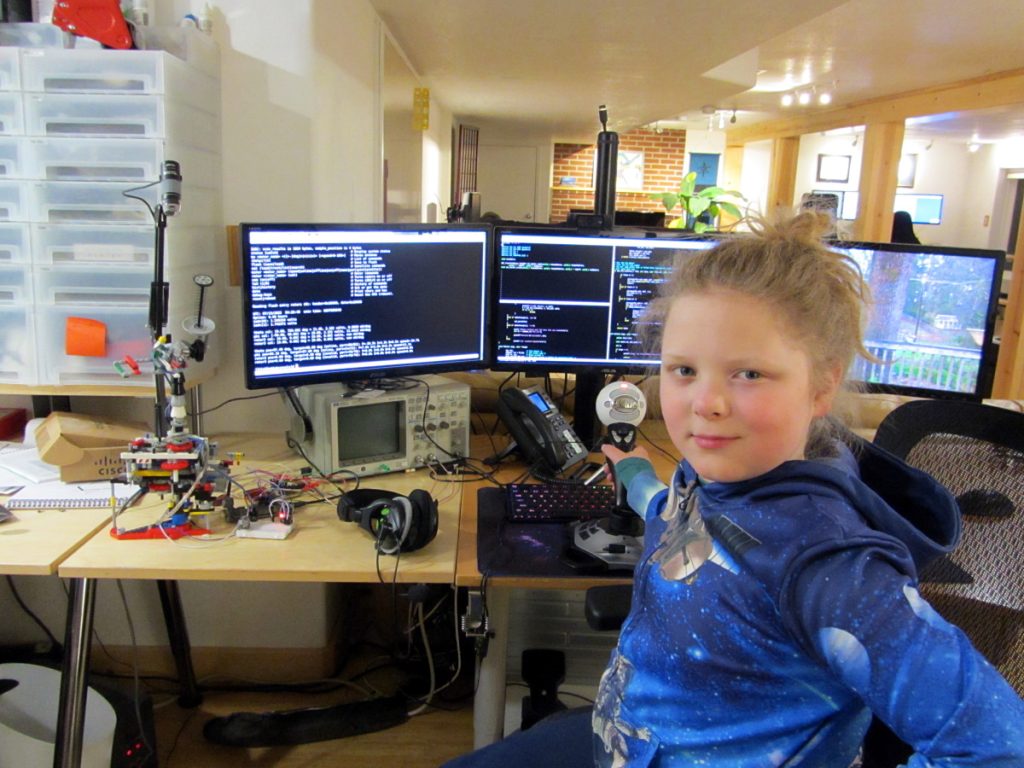
Zeke at his desk (Source: KJ7NLL)
The reason it was important to get this working properly is that the next stage was to implement some satellite tracking software that would determine the current location of a specified satellite, including the ISS, and keep the antenna pointing at that satellite as it races across the sky (travelling at a speed of 5 miles per second at an average altitude of 254 miles, the ISS orbits the Earth once every 90 minutes).
Actually, this might be a good point to pause and look at one of the videos on Zeke’s KJ7NLL YouTube channel. The video I’m thinking of is Track the Space Station and OreSat Satellites with a LEGO Rotor and Silicon Labs Micro-controller! (I also like the video that investigates the dielectric constant of cheese, which led me to suggest to Zeke that he might want to experiment with making a capacitor using two slices of ham separated with a slice of cheese—I’ll have to remember to ask him how that project is going).
“No man is an island,” as the English writer and Anglican cleric John Donne famously noted. One of the wonderful things about designing things today is that the internet opens the door to accessing all sorts of useful stuff. In Zeke and Eric’s case, their satellite tracking software made use of the following resources:
- Ryan Kurte’s efm32-base Github repository, which contains the Silicon Labs SDK to compile from the command-line using cmake.
- The sgp4sdp4 library that was ported from Pascal to C by Neoklis (5B4AZ) to track orbiting satellites. (Based in Cyprus, Neoklis has been a ham radio aficionado for decades, producing a tremendous amount of software from antenna simulators to satellite tracking algorithms.)
- Philip Salmony’s PID controller that sets the PWM duty cycle for each rotor to drive the antenna.
- The FatFs FAT/exFAT filesystem by ChaN.
As he noted in his video, Zeke has fully documented this project, including the software from the sources noted above—on his GitHub Space-Ham repository.
The final satellite tracking software created by Zeke and Eric runs on their EFR32MG21 microcontroller development board. They upload a two-line element set (TLE) file via XMODEM so it can track the position of any of the satellites listed at Celestrak.
As Zeke and Eric just told me: “Our software runs on the microcontroller itself, but we interact with the controller over a serial console. The device’s command line interface uses a USB-based serial emulation called CDC/ACM. Zeke’s desk computer runs Linux, which presents the microcontroller’s USB-serial CDC/ACM interface as if it were a modem. The microcontroller itself does not support USB, just TTL-serial, so we use the Silicon Labs WSTK debug interface to convert TTL-serial to USB ACM.”
They continued: “Of course, the MCU does not run Linux; it is a very small footprint platform with only 96k of RAM, so we wrote our own command line interface with an input function that interprets arrow keys using VT102 escape codes so as to select the satellite and configure other tunable options. The prompt itself acts like a modern command prompt with a command history and the ability to arrow through the prompt and add/edit/insert what you type, but of course it is far simpler than something like the GNU Readline library.”
Zeke tells me that he and Eric are on the final stretch. They are currently working on designing printed circuit boards (PCBs) for a triplexer and a low noise amplifier (LNA). They are tracking ham repeater satellites to verify that their tracking signal repeating is working as required. They also need to make some ISS prediction passes for when it will be in the sky long enough for a short (5-7 minute) conversation, and Zeke is going to prepare a set of questions to ask the astronauts and cosmonauts. When everything is ready to rock and roll, Zeke will transmit in the direction of the ISS and hope for a response!
I cannot wait for Zeke and Eric to finish this project and for Zeke to get to talk to the folks on the ISS. When that frabjous day comes to pass, I hope they will record the conversation so I can share it with you in a future column. In the meantime, as always, I welcome your insightful comments, perspicacious questions, and sagacious suggestions.


