

In my original O-M-Gosh, I’ve Been Zeked! column, I introduced 11-year-old Zeke who is currently engaged in using professional electronic design automation (EDA) tools to design radio frequency (RF) circuits to be used in conjunction with a giant helical antenna he’s building with the goal of communicating with the astronauts on the International Space Station (ISS). (Phew! I’m afraid that sentence got away from me towards the end.)
As I noted in that column, seeing what Zeke is up to has given me the sneaking suspicion that I’ve wasted much of my life and failed to reach my full potential. On the bright side, I find that I’m not alone, because I received a bunch of emails and LinkedIn messages from people saying that, after hearing about Zeke, they felt much the same way about their own lives.
Talking to his parents, Lara and Eric, I’ve discovered that Zeke has had an interest in space and understanding how things work from a very early age. As I previously mentioned, when Zeke was just one and a half years old, Eric took him down to their local Radio Shack where they purchased a small incandescent bulb, a battery holder, and a knife switch of the type favored by Igor and Frankenstein (“It’s alive! It’s alive!”).
In the image below, we see Zeke examining the knife switch (left) and intently watching Eric mounting everything on a piece of scrap wood (right). Once this was working, Zeke carried it around with him everywhere pointing out the elements “switch… battery… light…” over and over to anyone he could find. He also spent a lot of time in his closet delightedly turning his light on and off again.
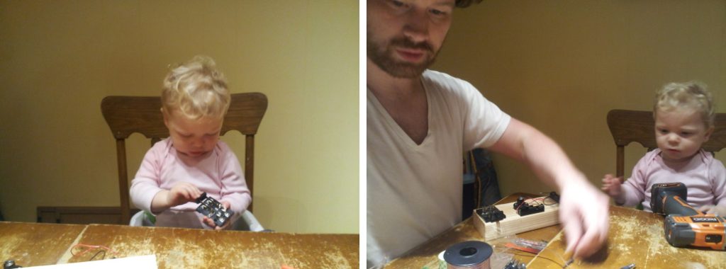
Zeke’s first introduction to electricity (Image source: KJ7NLL)
Lara says that it was around this time that, out of the blue, Zeke started gesticulating wildly and exclaiming in an incomprehensible language: “Wee-entwee. Hoth. Atmothfee. Hith it!” After increasing frustration over Eric’s lack of comprehension, Zeke finally got Eric to understand that he was referring to the space shuttle getting hot during re-entry into the atmosphere (“Re-entry. Hot. Atmosphere. Hits it!”). Since the final space shuttle flight took place in 2011, which was around the time that Zeke was born, he must have seen something on TV at a later date and subsequently synthesized and integrated this information.
As Lara told me: “Zeke’s curiosity followed the Industrial Revolution as his trajectory of interest grew from trains to cars and trucks, and then to airplanes, rockets, and spaceships. In pre-school he would design and launch rockets made from pencils, markers, and rubber bands and shoot them across the room. Fortunately, his teacher allowed and encouraged it so long as no one was standing in the line of fire.” But we digress…
Returning to the task of communicating with the ISS… Zeke has so many projects on the go at any particular time that it can be difficult to keep track of things, but I’ll take a stab at it.
Let’s start by reminding ourselves that Zeke passed his Technician-class Ham radio license in March 2020 when he was 8-years-old (he rarely fails to point out that he got a higher score than his dad, LOL). In April/May 2020, Zeke built a Yagi antenna and a Moxon antenna, which he gifted to his uncle and grandfather, respectively, to help them reach their local repeater towers.
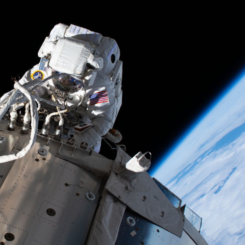
In June/July 2020, Zeke’s focus turned to helical antennas because—as he explained to me—these antennas are directional with maximum radiation occurring along the helix axis. Zeke went on to inform me that helical antennas radiate circularly polarized radio waves, which makes them useful for communicating with satellites.
One thing I’m extremely grateful for is that Lara keeps a photographic record of everything Zeke and Eric get up to (I only wish my own parents had had access to digital cameras when I was growing up). Let’s take a moment to feast our orbs on a few pictures documenting the creation of Zeke’s 10-foot-long helical antenna.
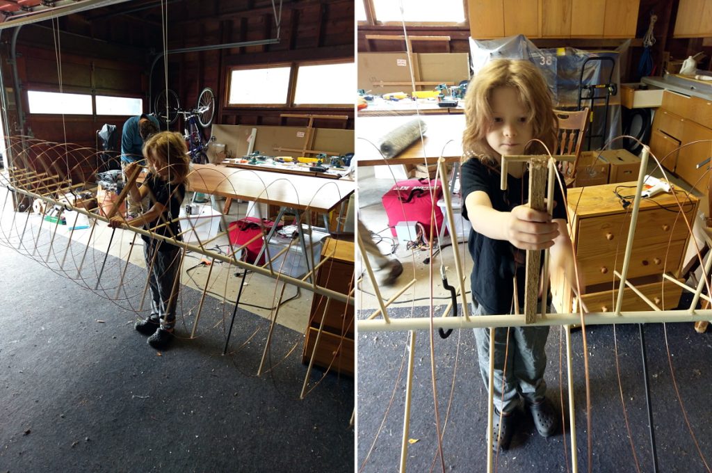
Zeke calibrating his 10-foot helical antenna (Image source: KJ7NLL)
An antenna rotor (or antenna rotator) is a device used to change the orientation of a directional antenna. One of the things about having a bigger antenna is that you need a bigger rotor to move it around. The term swap net (or swapnet) refers to a group of Ham enthusiasts who meet up “on the air” to buy, sell, or swap gear. After checking out a couple of swap nets, Zeke found someone who just happened to have two large rotors he was happy to donate to the cause. Unfortunately, the existing AC motors in these rotors had seen better days, but Zeke and Eric swapped these out with Lego motors that were more than adequate for the task.
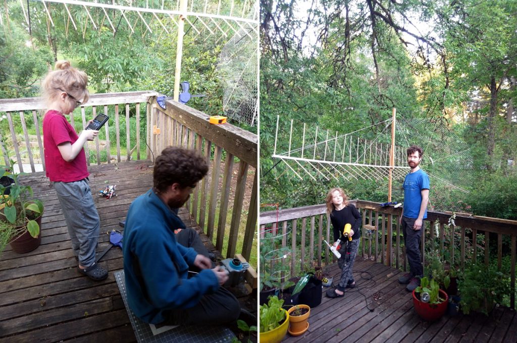
Mounting the 10-foot helical antenna on a refurbished rotor
(Image source: KJ7NLL)
Observe the chicken wire reflector at the far end of the antenna in the image above. Zeke explained to me that, if left to its own devices, a helical antenna will radiate out of both ends. Adding this reflector to one end causes the bulk of the radiation to come out of the other end of the antenna, thereby significantly boosting its range.
As an aside, while rooting through the images they shared with me, I ran across some showing a small 23-cm-long helical antenna. I foolishly assumed that Zeke and Eric had started with this little scamp as a proof of concept (POC), and that it was only after they’d got this working that they’d scaled up to their 10-foot-long whopper.
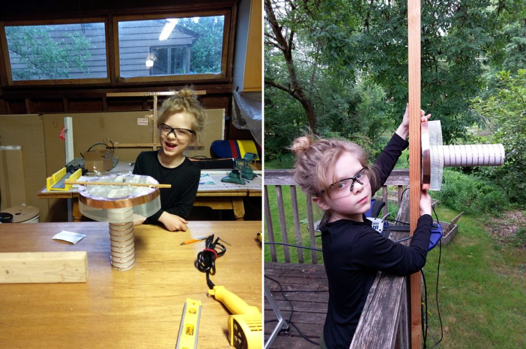
Zeke pleased with the progress on his 23-cm helical antenna (left) and mounting the antenna (right) (Image source: KJ7NLL)
Once again, however, I discovered that Zeke and I have more in common than you might suppose because I can never persuade myself to “start small”; instead, I always “go for broke” and leap headfirst into the fray with gusto and abandon (and aplomb, of course). Similarly, it was only after Zeke and Eric had finished their 10-footer that Zeke happened to spot a piece of recyclable tube lying around and decided to build a 23-cm helical antenna on a whim.
Now, this is where things started to get a bit confusing for me, because Zeke was also involved in multiple other projects at the same time. The problem is that he bounces around from project to project in his conversations leaving me unsure as to which bits go where (now I know how my wife—Gina the Gorgeous—feels when I’m regaling her with tales of my own cunning creations).
For example, one of Zeke’s side projects, which he commenced circa October 2020, was to start constructing a 6-band high-frequency (HF) radio kit, but he quickly concluded that six bands weren’t sufficient for his purposes, so he decided to extend things to 11 bands. In addition to winding his own inductors, Zeke used AWR Microwave Office to design a circuit board to select between the different inductors.
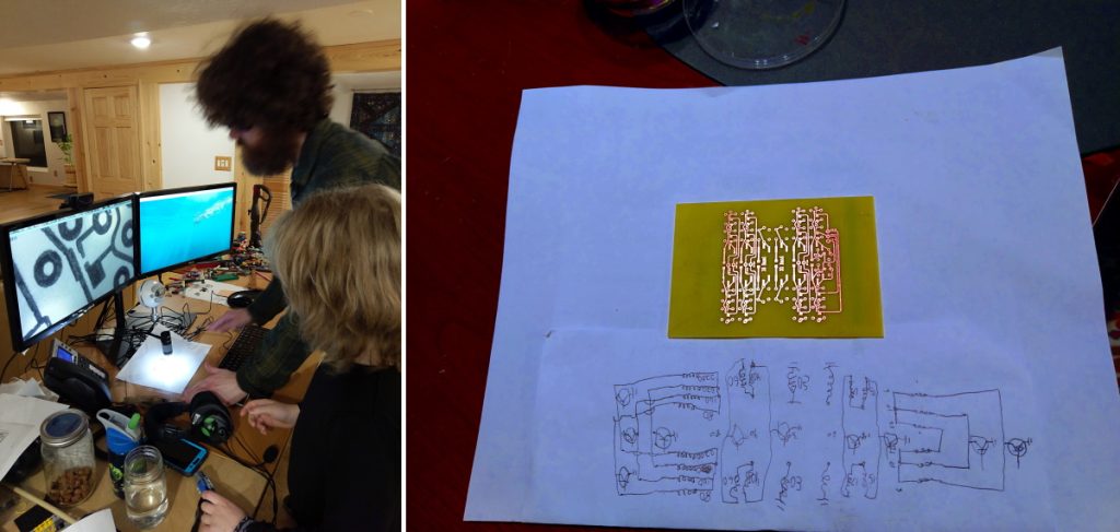
Inspecting the traces with microscope after etching the SSB circuit board (left) and the completed board showing Zeke’s original hand sketch of the circuit (right) (Image source: KJ7NLL)
Did you notice the “SSB” portion of the caption above? One of the things I’ve noticed is that, like most professional engineers, Zeke’s conversation is replete with TLAs (three-letter acronyms). Unfortunately, I fear that Zeke isn’t overly convinced with regard to my own bona fides as an engineer because I’ve noticed that whenever he drops an abbreviation like SSB into the conversation, he’ll pause and say it out in full (“SSB stands for single-sideband”) to make sure I’m keeping up with him.
As if this weren’t enough, at the same time as Zeke was working on his HR radio project, he also took (and passed) the exams for his General-class Ham license.
A couple of months later, in January 2021, another topic that caught Zeke’s attention was the concept of using a phased array antenna to implement beam forming, which means you can control the direction of the radio signal without having to physically move the antenna. Part of this involves using power amplifiers. NXP makes appropriate amplifiers, but they aren’t impedance matched. Happily, AWR Microwave Office supports NXP, and vice versa, so Zeke started to design his own phased array antenna.
I think it was around this time that Eric called for a pause. He explained to Zeke that if they kept on working on all three projects, they would be dissipating their energies, and it would be better for them to focus on one project at a time (this is advice I could use myself). Remembering that Zeke’s original goal was to talk to the astronauts on the ISS, it didn’t take long before they decided to put the HF radio and the phased array antenna projects on the back burner for a while.
There’s so much more to talk about, but I’m afraid I may have talked too long already, so we will leave the topics of Zeke designing a motor controller board and creating his proof-of-concept satellite tracking system (hardware and software) for a future column. In the meantime, I’d like to share some videos with you that Zeke shared with me (they are also available on his YouTube channel).
The first is a video of Zeke’s recent lecture/demo to about 30 members of the local amateur radio club. A large portion of the group remained after the demo for another hour in order to verify that his ISS tracker did indeed indicate when the ISS was overhead (the ISS circles the globe every 90 minutes).
This begins with still images, but it transfers into video after less than a minute. In fact, there will need to be a follow-up video to explain “the making of this video” due to the Herculean effort Zeke used to splice together audio, slides, and video from three separate sources (he taught himself to do all this—thanks, YouTube!).
Three related offerings are: Build a HUGE a Helical Antenna, Mount it on Your Deck!, Make a Circuit Board with a Toaster Oven!, and How to 50- Ohm Impedance Match and Test with Microwave Office.
And here’s just one more video that shows Zeke is a man after my own heart because he decided to investigate the dielectric constant of cheese (I love cheese).
This caused me to contemplate what the dielectric of English Stilton cheese might be, but I know deep down that I will never find out because I like this savory delight so much that it would be eaten before I got to employ it in an experimental capacity. I emailed Zeke to ask if he was working with real cheese or “American Processed Pseudo-Cheese,” and he immediately (and indignantly, I feel) replied: “It was thin-sliced organic cheddar!” (The exclamation point made his point. I felt so foolish.)
All of this caused me to inquire if Zeke had seen the stop-motion animations about Wallace and Gromit by Nick Park. The first three—A Grand Day Out, The Wrong Trousers, and A Close Shave—have long been on my “must see” list when I’m sharing suggestions with others (I can hear Wallace saying, “More cheese, Gromit?” in my head as I type these words).
A few days later, Zeke emailed me to say that his mom had picked up the Wallace and Gromit videos from their local library and he is now as big a fan as yours truly (all three of these animations, plus one more, are available on the iTunes Store for only $7.99).
Well, I think we will leave things there for the moment. As always, I welcome your creative comments and insightful questions.


