

As you may recall from my previous “O-M-Gosh, I’ve Been Zeked!” columns, 11-year-old Zeke is on a mission to talk to the astronauts and cosmonauts orbiting the Earth on the International Space Station (ISS). He started by getting his ham radio license when he was only 8 years old, and now he’s working on getting his 10-foot helical antenna to track the space station.
In Part 1 of this mini-mega-series we met Zeke and his dad Eric and learned how this odyssey all began. In Part 2 we saw how Zeke and Eric built the first incarnation of their 10-foot helical antenna and mounted it on their deck. Since then, I’ve been chatting with Zeke and Eric some more, and I thought it might be useful to fill in some of the gaps and bring us up to date with the current state of play.
Sometime after receiving his ham license, Zeke heard about Kids Net (a local ham radio network for kids), but when he joined there was an echo, which indicated that his signal was being scattered. The solution was to create a directional antenna and—at the end of the Kids Net meeting—someone suggested a Moxon Rectangle, which is a simple and robust single-frequency antenna. Zeke and Eric quickly built such an antenna, as illustrated in the image below.
Zeke’s Moxon antenna (Source: KJ7NLL)
Of course, the thing about a directional antenna is that you have to point it in the right direction. This would have been a simple task if Zeke had wished to use it to talk only to the Kids Net, but he also wanted to use it to communicate with other nets. Rather than reposition the antenna by hand, Zeke and Eric decided to build an antenna rotor (or antenna rotator), which is a motor-driven device used to change the orientation of a directional antenna.
As fate would have it, when Zeke was starting to develop an interest in technical Legos as a kid (well, as an even younger kid than he is now), Eric managed to scoop up twenty 1990-era teacher edition Lego Dacta Kits intended for science classrooms. As Eric told me, “We got them for a steal at a garage sale and—years later—they are still being used for our various projects.”
Using a Lego motor to rotate the Moxon antenna (Source: KJ7NLL)
Initially Zeke just used a switch to control the motor to point the antenna in the right direction. The next step was to add a potentiometer that could be used to report the position of the antenna. Eric and Zeke pointed the antenna as far as they wanted it to go in one direction and noted the compass bearing (number of degrees) and the corresponding value on the potentiometer. Then they rotated the antenna as far as they wanted it to go in the other direction and note the corresponding degrees and potentiometer readings.
Their next step was to create an Excel “cheat-sheet” that performed a linear interpolation of degrees and potentiometer values. Now Zeke could easily determine the pot value associated with a desired direction from the spreadsheet, and then use his multimeter to read the pot as he controlled the motor. Their latest and greatest solution for the helical antenna is significantly more sophisticated, but I find it interesting to track the evolution in Zeke and Eric’s implementations.
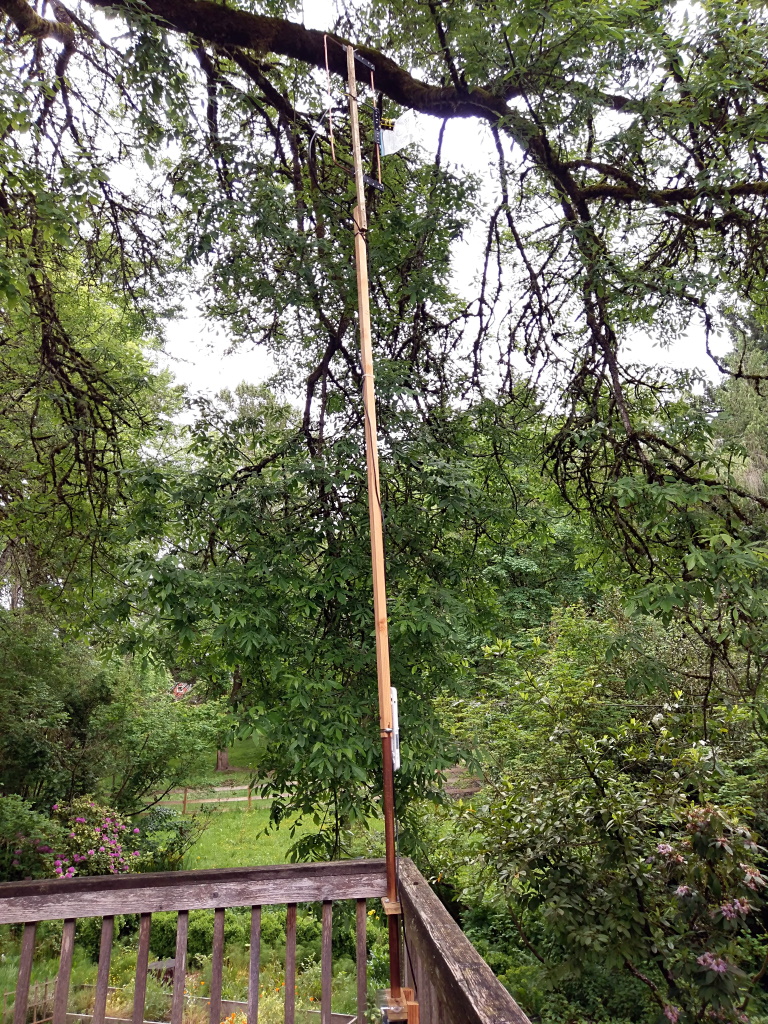
We talked about the creation of the first-pass implementation of Zeke’s 10-foot helical antenna in my previous column. The rotor he used for his small Moxton antenna wasn’t adequate to drive the much larger helical antenna. However, while on a swap net—a net where ham enthusiasts meet up “on the air” to buy, sell, or swap gear—Zeke found someone who had two large rotors that he was happy to donate to the cause.
The plan is to use one rotor to control the azimuth value of the antenna (it’s rotational direction) and the other to control its elevation. Sad to relate, the existing AC motors in the rotors had seen better days, so Zeke and Eric discarded them, after which Eric implemented a few judicious modifications on the rotor housings with a Dremel.

Modifying the new rotors with a Dremel (Source: KJ7NLL)
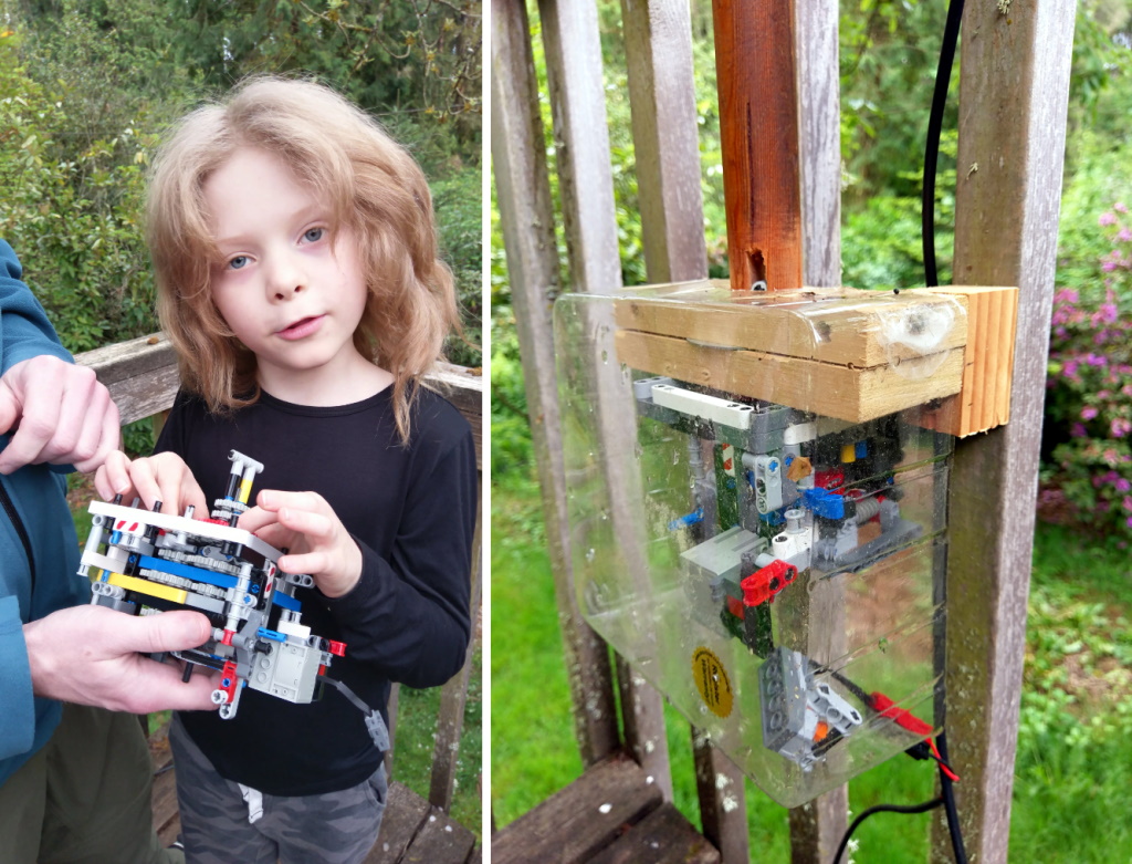
As we see in the image above, Zeke and Eric saved the existing gear trains, which can provide more than enough torque to drive the antenna. For each rotor, they added a DC Lego motor to drive the antenna and a potentiometer to read the current position.
At the same time, Zeke was using AWR Microwave Office from Cadence to design the motor control board that will also be mounted in the rotor casings. Unofficially, he calls this board, which he etched himself, the “rocket” board because of its shape.
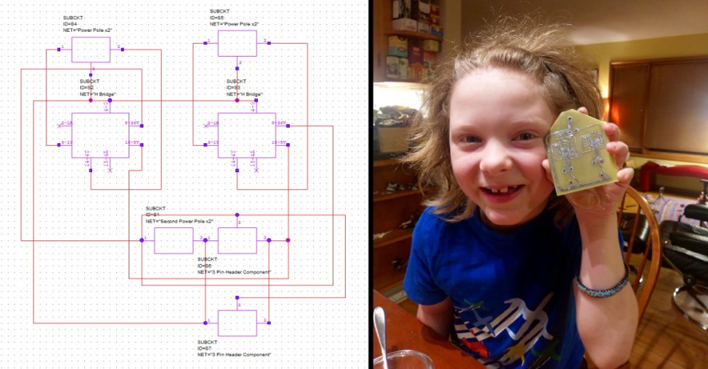
Designing and etching the “rocket” board (Source: KJ7NLL)
The image below shows a Lego model of the antenna (left) with two motors used to control its azimuth and elevation. This provides a testbed for Zeke and Eric to test their control algorithms. On the right of the image we see a more detailed (if slightly blurry) view of the rocket board with its H-bridges and voltage regulator on the left, a EFR32MG21-based microcontroller development board from Silicon Labs in the middle, a real-time clock (RTC) board just next to the microcontroller on the right, and the Lego model in the rear of the image.
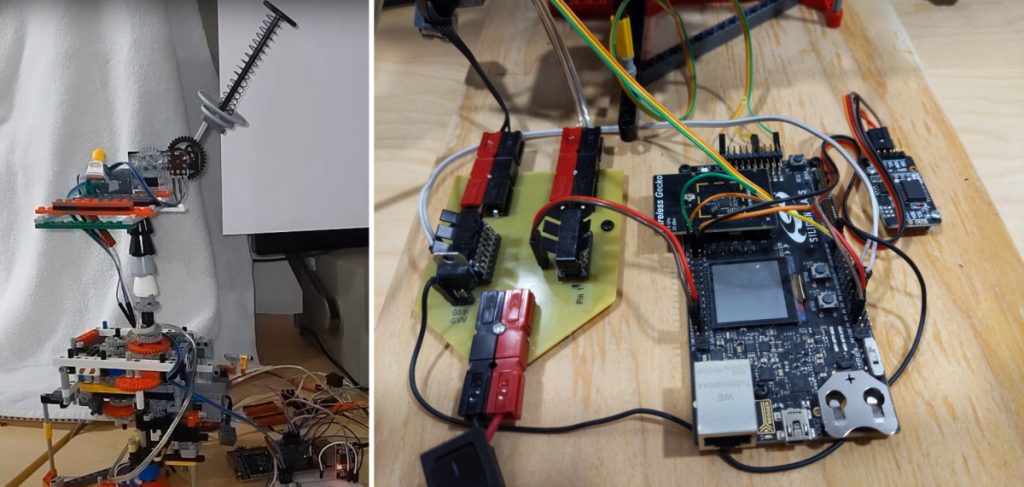
First tests on the motor control algorithms (Source: KJ7NLL)
With respect to their choice of microcontroller development board, Eric notes: “Right now, the antenna rotor is controlled through a serial command line interface. However, the controller will ultimately be on the deck and the ham radio is 60 feet away, so we need a way to communicate with it remotely. We chose the EFR32MG21 because it includes Bluetooth that we will send down the feedline for the antenna, so we can connect to the serial interface over Bluetooth.”
Furthermore, with respect to their motor control algorithms, Zeke started out simply by using his potentiometer readings to determine where the antenna was currently pointing, using his satellite tracking software (which we will discuss in more detail in a future column) to determine where he wanted the antenna to be pointing, and then using the differences to decide what to do with the motors.
Not surprisingly to those of us whose degrees are in Control Engineering (why, that would be me), this resulted in the model antenna hunting around its desired position without settling down. Zeke says the problem was even more noticeable with the full-size antenna, whose inertia would cause it to move towards its intended direction, overshoot its desired position, start to correct itself, overshoot again, and… you can see where this is going. It was at this point that Eric introduced Zeke to the concept of proportional–integral–derivative (PID) control algorithms, which is what they are now using.
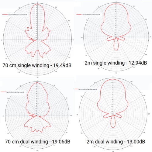
But wait, there’s more, because the original helical antenna that Zeke and Eric built had only a single very high frequency (VHF) winding to talk to the ISS on the 2-meter band. However, it turns out that the ISS also has an ultra high frequency (UHF) repeater that allows other people to listen in on their conversations (I plan on doing so myself when Zeke finally gets to talk to the ISS).
As part of this, Zeke and Eric wondered if adding a coaxial secondary 70cm UHF winding to their antenna would interfere with the primary 2m VHF winding. In order to evaluate this, they turned to a state-of-the-art 3D electromagnetic (EM) simulation software tool in the form of the Clarity 3D Solver from Cadence.
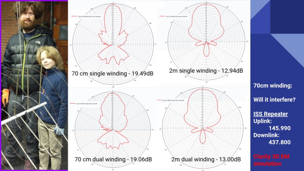
Using Cadence Clarity to simulate dual helical windings (Source: KJ7NLL)
The results showed very small attenuations between using single and dual helical windings, where such attenuations would not significantly degrade the main signals. As a result, Zeke and Eric added the second helix as shown on the left of the above image.
I’m sorry. I was intending to talk (some might say “waffle”) about the software Zeke and Eric are using to track satellites in general and the ISS in particular, and how they are using this information to control their (now dual) helical antenna, but I fear I got carried away with all of the other stuff they’ve been showing me. I promise that software will head the agenda in my next “O-M-Gosh, I’ve Been Zeked!” column. Until that frabjous day, as always, I welcome your insightful comments, perspicacious questions, and sagacious suggestions.


