


There’s a big change coming in the automotive world. “Duh,” you say? “Um, hello! Self-driving!” you insist? Well, yes, that too, but that’s not the change I’m talking about. This change applies whether self-driving ever happens or not.
It’s electrification. Drive-by-wire. As we alluded to last week. Replacing mechanical linkages with electrical signals. (So, yeah, your battery better never die, or else you can’t do anything that you used to be able to do with a dead battery… I’m pretty sure my car can’t set the e-brake without power…)
While this affects any manner of cars powered by internal-combustion engines, it’s an even bigger deal for – and here your “Duh!” is appropriate – electric or hybrid vehicles. Cuz electric motors and batteries and high currents moving around.
But even without this big move to the power of the electron, technology has been helping to make engines and other operations more efficient. And one small part of that is the use of magnetometers to measure position – either linear or angular. They may also be used as switches or controllers of some sort. So you have shafts or some other mechanical thingamawhatchers with one or more magnets and then one or more sensors to detect those magnets.
Sounds straightforward, right? I mean, in industry, we’ve been doing this forever, right?
Yeah, but with this increased electrification – and, in particular, with some of these vehicles moving high currents around and stopping or starting them, well, you end up creating some measurable – but unrelated – magnetic fields around the wires and such. And those unintentional magnetic fields can muck about with the intentional fields you’re trying to read with the sensors.
These are referred to as stray magnetic fields, and they’re a big enough issue that magnetometer makers have found ways to eliminate those fields and then market that as a feature. We look at two different approaches to this today.
Strays, Not Anomalies
Before we do so, however, I need to debunk a notion that certainly popped into my mind when I first saw a press announcement about one of these. Back when everyone seemed to be talking about location services and navigation, we would make mention of the magnetic anomalies that could confuse a magnetometer. One of the blessings of sensor fusion is that, in an IMU, the magnetometer helps to correct gyroscope drift, while the gyro helps to reject magnetic anomalies.
So my first thought was, “Aha! Is this a solution to that whole navigation-near-an-elevator problem?” And the answer is: no. Magnetometers intended for measuring the earth’s relatively weak magnetic field must be pretty sensitive. The applications we’re talking about measure the stronger local magnetic fields from the intentionally placed magnets. In addition, thinking more, you realize that, if there’s ever a definition of a background (if not exactly stray) magnetic field, it would be the earth’s field. If you’re building a compass, then rejecting that background field would be, shall we say, counterproductive.
So no, this isn’t about those kinds of “stray” fields.
The two relatively recent magnetometer announcements I’ll cover here are from TDK’s Micronas division and AMS. TDK’s new Micronas HAL® 39xy position sensor family features a multi-mode magnetometer that can be programmed for linear, rotary, and fine 3D measurements. It provides both field strength and angle measurements.
Meanwhile, AMS announced their AS5200L, a dual-die magnetic rotary position sensor, earlier last year. It provides only the angle measurement. That said, they say that all of their position sensors, not just this one, reject stray fields.
Both devices have multiple Hall-effect sensors, which allows them to determine the direction of the measured fields. The AMS sensors measure the field in the z-direction; TDK includes a vertical sensor for 3D measurements. So these devices are different, perhaps even addressing different problems (although the TDK device can presumably be configured to do what the AMS device does).
Unrelated to that difference, however, is the fact that they also have two different ways of handling stray-field rejection. TDK claims to be the only one that can reject both homogeneous and gradient background fields, but AMS says that they can handle the types of gradients typical in stray fields because the gradient isn’t that sharp; at the scale of the sensor, it looks almost homogeneous.
Before these types of devices, the standard way of handling the issue has been to place a magnet over the sensor die. You’re then measuring its interaction with the other magnet. To protect against other fields, they need to shield the device. With built-in stray field rejection, you can simplify the design and reduce the cost (assuming the new sensors are priced in a way that doesn’t wipe out the savings).
TDK has an operational approach to the problem, and it’s pretty straightforward. During test, they calibrate their sensors and store the results in non-volatile memory. In an actual measurement, that stored value is used as a correction.
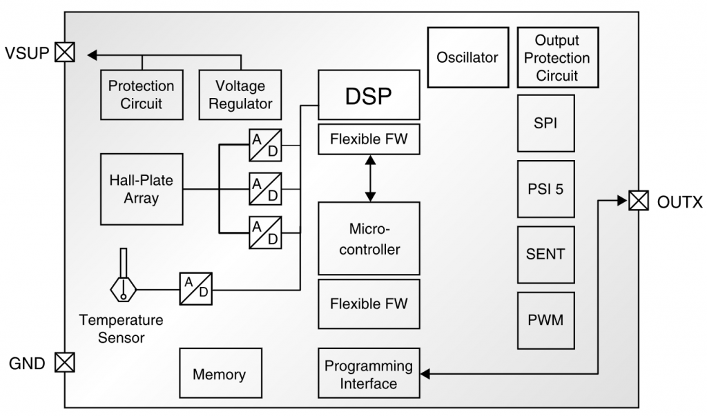
(Image courtesy TDK Micronas)
AMS’s approach is structural rather than operational. They do a differential measurement of the combined field into and out of the chip. The thing is, however, that the stray field will be the same on both ends (even in a slowish gradient across roughly 2 mm), so it becomes a common-mode signal that cancels out.
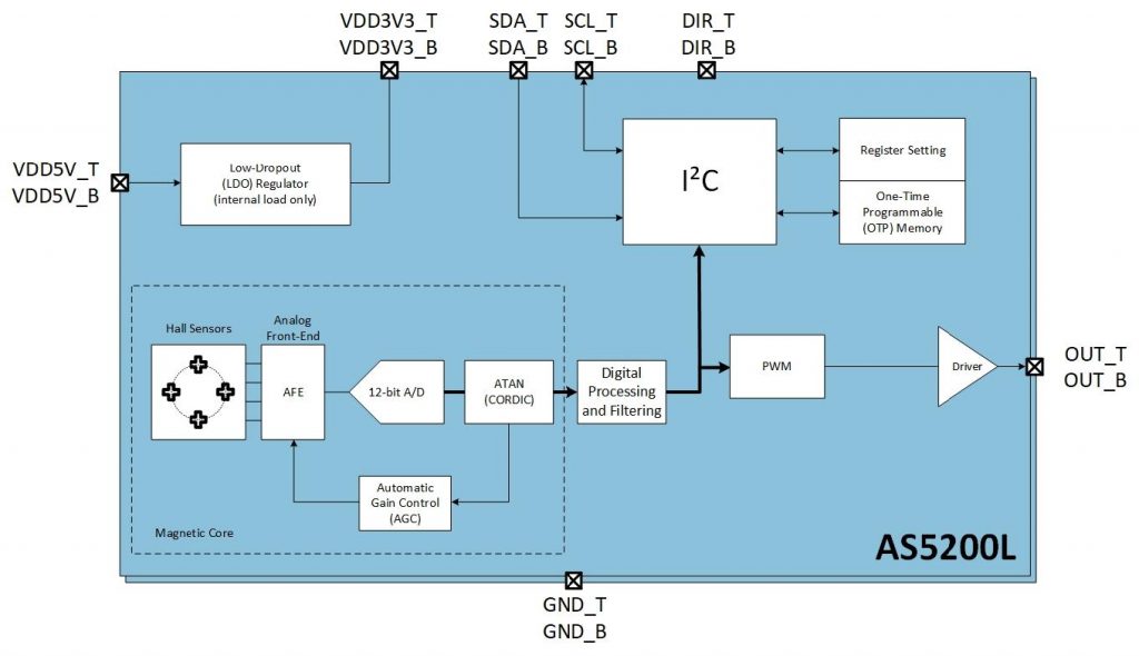
(Image courtesy AMS)
Even more unusual is AMS’s dual-die approach, by the way. They’re specifically addressing the automotive market – heck, it’s more specific than that: this sensor is designed to measure shifter position. So it’s very focused on one application – but one that has to be extremely reliable. They say that they’ve proven their reliability the usual way (through testing), but that in order to pass muster with ISO 26262, they need redundancy.
So they stack two identical dice, one atop the other. They measure from the two dice in turn, but the leads aren’t combined so that if there’s, for instance, an issue with the power lead to one of them, the other can keep working. You can do the job just fine with a single die for other applications; it’s just that the ISO folks won’t be happy.
Note on capitalization: AMS prefers to be called “ams,” and their logo reflects that. But I have a hard time pretending that proper nouns aren’t actually proper nouns, and, in English, proper nouns are capitalized. In the US, acronyms tend to be all-caps; in the UK, they’re often only initial-cap. So, just to be clear, I’m simply using the company name as a proper noun, not as a reflection of the logo.
More info:


What do you think of these two ways that magnetometers can combat stray magnetic fields?