

Yes! This is it! At long last we’ve reached the final part of this epic saga into all things related as to why switches bounce and how to mitigate against this phenomenon; that is, how to debounce the little rascals.
On the off-chance you’ve only just run across this modest magnum opus, we should perhaps commence by noting that in Part 1 we introduced the fundamental concepts of switch bounce and in Part 2 we delved deeper into the bouncing associated with single pole, single throw (SPST) and single pole, double throw (SPDT) switches.
Later, in Part 3, Part 4, and Part 5 we considered how to debounce our switches using RC networks, monostable multivibrators, and latches, respectively. In Part 6 we introduced some special switch debounce integrated circuits (ICs), and in Part 7 we cogitated and ruminated on using switches with resets, switches with interrupts, and polling vs. interrupt-driven techniques.
Most recently, in Part 8, we considered FPGA (hardware) solutions to the switch bounce problem, and we also started to ponder MCU (software) solutions. In this column, we will dive deeper into the software solution space (where no one can hear you scream), but first let’s note that, if you find any of the switch terminology used here to be unfamiliar, you might want to peruse and ponder the associated Switch Types and Switch Terminology columns.
Software Solutions (Recap)
Before we hit the ground running, let’s briefly remind ourselves of a couple of points. First, I’m a hardware design engineer by trade, so you aren’t allowed to laugh at and/or criticize my code. Second, for the purposes of these discussions, we are assuming we are working with a single switch — we can scale our solution to handle multiple switches later.
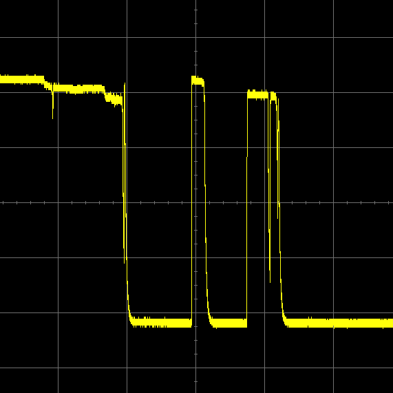
In the previous column, we considered quick-and-dirty software solutions in the context of SPST and SPDT switches. In the case of the SPST switch, for example, we started by pondering a waveform as illustrated below:
Switch bounce on an SPST-NO toggle switch without noise (Image source: Max Maxfield)
Our laughably simple first-pass solution was to check if the switch had just changed state, which would indicate the leading edge of a (potentially bouncing) transition. As part of this, we determined in which way the switch signal was transitioning (0-to-1 or 1-to-0), thereby allowing us to perform different actions when the switch was closed and opened, if we so desired.
One huge problem with our first-pass solution was that, after performing whatever actions we wished on seeing the first transition, we called a delay() function to wait for the switch to stop bouncing. In our code, we defined a constant called MAX_BOUNCE and assigned it a value of 20, which we took to represent 20 milliseconds (ms). Thus, the delay value we used was (MAX_BOUNCE * 1000), which equates to 20 ms (the reason for using this value is discussed in excruciating detail in earlier columns). The thing is that the delay() function is a blocking function, which leaves the microcontroller twiddling its metaphorical thumbs for the duration of the delay, thereby blocking it from doing anything more useful.
Too Noisy!
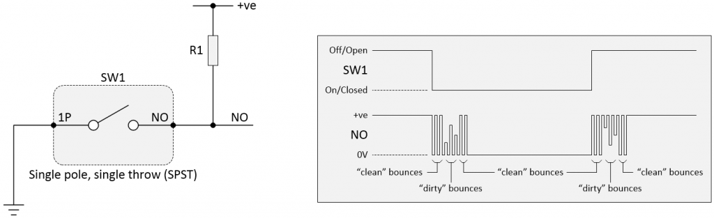
Have you spotted the fly in the soup or the elephant in the room (I’m feeling generous, so feel free to pick whichever metaphor you prefer) with regard to our quick-and-dirty solution described above? The problem is that, as discussed in previous columns, any switch debounce solution we use should really be able to deal with a noisy signal. Consider the waveforms shown below, for example:
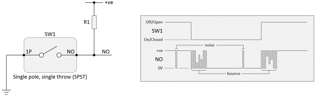
Switch bounce on an SPST-NO toggle switch with noise (Image source: Max Maxfield)
If our cheap-and-cheerful program was unfortunate enough to read the input during a noise spike, it would mistakenly assume this was the leading edge of a (potentially) multi-bounce transition and react accordingly.
Whichever way you look at it, this is almost certainly going to cause problems. As one simple example, suppose the time between the noise spike and the start of the switch transition was greater than our 20 ms value. In this case, in addition to our program leaping into action before such action was actually justified, by the time the switch actually did start to transition, the program would mistakenly believe the switch to be in the opposite state to its real-world condition, at which point confusion would ensue.
Dump the Delay()
Before we begin to consider more sophisticated software solutions, the first thing we need to do is to dump the delay() function. The approach I use in my hobby projects is to define some master clock “tick” — say once every millisecond — and to use this tick as the impetus to perform any actions, including checking the state of any switches. Remembering that you can’t laugh, the Arduino-inspired pseudo-code for this might look something like the following:
#define TICK 1 // Tick time = 1 ms
#define MAX_BOUNCE 20 // 20 ms
uint32_t PreviousTime;
void setup ()
{
PreviousTime = millis();
}
void loop ()
{
uint32_t currentTime;
currentTime = millis();
if ( (currentTime – PreviousTime) >= TICK)
{
// Do stuff with switches
// Do other stuff
PreviousTime = currentTime;
}
}
The Arduino’s millis() function returns the number of milliseconds since the program started running. With regard to MAX_BOUNCE, depending on how we decide to play things, this could be used to say that we are sure the switch will have stopped bouncing 20 ms after the first switch transition, or it could be used to wait until 20 ms after the final switch bounce.
Count on Me!
One approach to debounce that’s quite interesting is to use a counter. In order to keep things simple, let’s assume that we start by looking for a 0-to-1 transition and that we are confident the switch will have stopped bouncing by 20 ms after the final transition.
The idea here is that when we see the first transition from a 0 to a 1 on the signal from the switch, we clear our counter to 0. Every time we execute our 1 ms loop, we re-read the value on the switch. If the value is 1, we increment the value of the counter; if the value is 0, we clear the counter to 0.
When the counter eventually contains a value of 20, we know the signal from the switch has remained in its 1 state for 20 ms, at which point we can execute any actions we deem to be appropriate.
Now we would start to look for the switch to be toggled the other way in the form of a 1-to-0 transition. When this occurs, there are a couple of obvious ways we could go. One option would be to start by clearing the counter to 0 as before. This time, however, every time we cycle round the loop, if the switch is 0 we increment the counter and if the switch is 1 we clear the counter; and we wait for the counter to reach 20. The alternative would be to commence by loading the counter with 20; in this case, every time we cycle round the loop, if the switch is 0 we decrement the counter and if the switch is 1 we reload the counter with 20; and we wait for the counter to reach 0.
Depending on how we write our code, a counter-based solution can also tolerate noise. Assume our code acts as described above, for example. In this case, if we are waiting for a 0-to-1 transition and we see a noise spike of 1, although this will initiate the count, the counter will be repeatedly reset to 0 for every subsequent pass through the loop until the switch commences its real 0-to-1 bouncing transition.
Vertical Counters
There’s always something new to learn. For example, reader Ben Cook of Airspeed Electronics kindly took the time to inform me that his personal favorite switch debounce solution came in the form of “Vertical Counters.”
Well, this certainly sounded jolly interesting, but — prior to Ben’s communication — I wouldn’t have recognized a vertical counter if one had crawled up my leg and sank its teeth into an unfortunate part of my anatomy, so I asked Ben to elucidate.
Ben replied as follows: “I can’t take any credit for the idea. I just read about it a while ago and have used it in a recent project. It’s a neat trick. You can learn more about Vertical Counters here.”
Not Too Shifty!
Another interesting approach is to use a shift register. Let’s assume we have a 32-bit unsigned integer variable that we are going to treat as being a shift register. Let’s further assume that we are waiting for a 0-to-1 transition on our switch, and that we therefore commence by clearing our shift register to 0.
Every time we circle round our 1 ms loop, we shift the current 0 or 1 value from the switch into the least-significant bit (LSB) of our shift register. Next, we use the & operator to logically AND our shift register with 0x000FFFFF (thereby removing any “noise” in the most significant bits of the register), and we compare the result to 0x000FFFFF.
If any 1 noise spikes occur prior to the switch commencing its 0-to-1 transition, or if the switch starts to bounce, any random 1s and 0s will work their way through the shift register, which is essentially being clocked every ms by our loop. It’s only when the shift register ANDed with 0x000FFFFF contains 0x000FFFFF that we know we’ve had a series of twenty 1s and that our switch has therefore been in a stable 1 state for 20 ms.
At this point we start to look for a 1-to-0 transition on the switch. One way to do this is to preload the shift register with 0x000FFFFF. Every time we circle round our 1 ms loop, we shift the current 1 or 0 value from the switch into the LSB of our shift register. Once again, we use the & operator to logically AND our shift register with 0x000FFFFF (thereby removing any “noise” in the most significant bits of the register), and we compare the result to 0x00000000.
In this case, if any 0 noise spikes occur prior to the switch commencing its 1-to-0 transition, or if the switch starts to bounce, any random 0s and 1s will work their way through the shift register, which is essentially being clocked every ms by our loop. It’s only when the shift register ANDed with 0x000FFFFF contains 0x00000000 that we know we’ve had a series of twenty 0s and that our switch has therefore been in a stable 0 state for 20 ms.
But Wait, There’s More!
As I mentioned earlier, there’s always something new to learn. For example, I was just bouncing around my chum Jacob Beningo’s website, as you do, when I ran across two switch bounce related articles: A Reusable Button Debounce Module and 7 Steps to Create a Reusable Debounce Algorithm.
I’m not sure if Jacob explicitly said this, but one thing I took away from these articles is the idea of separating out the task of keeping track of the button states from actually using those states.
I’m still trying to wrap my brain around this, but — still thinking in terms of the Arduino — I’d continue to have my 1 ms loop cycling around reading the states of any switches and performing switch debounce using either the shift-register or counter-based techniques discussed above. However, I’d augment this with some sort of GetSwitchState() function that I can use to access the state of a named switch, like GetSwitchState(BigRedSwitch), which will return enumerated values along the lines of SWITCH_IS_CLOSED, SWITCH_IS_OPEN, SWITCH_JUST_CLOSED, and SWITCH_JUST_OPENED (or, in the case of a push-button, BUTTON_IS_PRESSED, BUTTON_IS_RELEASED, BUTTON_JUST_PRESSED, and BUTTON_JUST_RELEASED).
The idea is that this would increase the readability and understandability of the main program, because we could use a statement like if (GetSwitchState(BigRedSwitch) == SWITCH_JUST_OPENED) to initiate some action, where the act of testing the state of the switch would also change its state from SWITCH_JUST_OPENED to SWITCH_IS_OPEN.
Again, I’m still in the early stages of mulling this over, so if you have any thoughts or suggestions, this would be a great time to share them in the comments below. Until next time, have a good one!


Regarding the code snippet shown above for a method of debouncing, I appreciate it is just a prototype of actual usable code, but there is a subtle flaw which needs to be addressed.
I came across this problem in my last project where I was using Visual Basic under Windows to control some test equipment. I needed to time various operations & was using a Windows timer in a similar process.
The problem arises if the timer overflows between the start of the operation and the anticipated end time. If the code is used “as is” & overflow occurs, the debounce time will be impossibly long, leading to incorrect operation of the switch.
The solution is to add another test for timer overflow. The code for this can be found on language reference websites that refer to the operation of hardware timers.
I really enjoyed these discussions on switch debouncing, but I was uncertain if the techniques discussed applied to my problem. I have a discarded spectrometer with a very sophisticated gear driven apparatus to rotate a diffraction grating. A cam activates a microswitch every time the grating has been rotated 10 Angstroms. I have access to two wires coming from the spectrometer which are activated by a relay connected to the microswitch. I would like to keep count of the 10 Angstrom markers to help me in the wavelength calibration process. I do detect bouncing when the switch is activated but I also noticed that the two wires are carrying an 8 volt p-p 60cps signal, which I assume is from the relay coil or a transformer inside the case. I don’t want this AC voltage to influence the counting of the microswitch transitions. I connected a 10 uF electrolytic across the two leads, which worked fine for a while but soon I could not detect any switch transitions at all. Does anyone have any suggestions that might help me resolve this problem? I would really appreciate any suggestions you might have. Thank you!
Hello Max!
Excellent series of articles! You should also mention the importance of the so called wetting current:
https://en.wikipedia.org/wiki/Wetting_current
I have a kitchen oven with a switching contact where only microamperes flow to the (incorrectly designed) electronics. Its contacts regularly get dirty and I have to take the switch apart and clean it.
The more heavily loaded contacts of the same switch do not have these problems. It took me a long time to figure out this problem!
That’s a great suggestion — if I ever revisit this topic I will add “wetting current” into the mix. There’s so much more to switches than most people imagine 🙂
Yes! And when it comes to relais … you know why sometimes a zener diode is put in series with the freewheling diode that is always parallel to the coil?
I made a quiz out of this question:
https://www.embeddedrelated.com/showquiz/34