

Previously, as they used to say at the start of a new episode in a TV series, we discussed the history behind the use of hardware vs. software to debounce our switches. We also perused and pondered the idea of using an RC network followed by a Schmitt trigger to debounce a single pole, single throw (SPST) toggle switch (see Part 3). Actually, if you’re feeling in a nostalgic mood, you might also want to revisit Part 1 and Part 2, along with my Switch Types and Switch Terminology columns.
My previous column triggered a flurry of comments and questions. For example, regarding hardware vs. software solutions in commercial projects, university lecturer and freelance engineer James Langbridge emailed me to say:
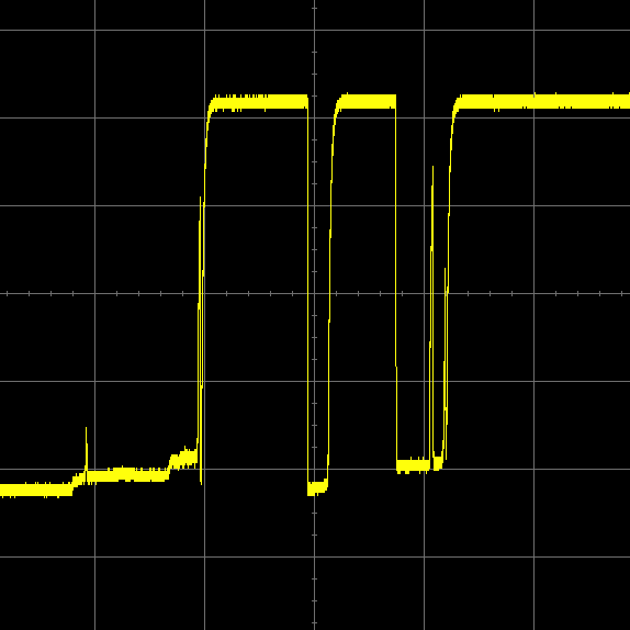
Switch bounce is one subject that some students do have a problem with. It always amazes them when we look at the output from a switch on the oscilloscope. As for the debounce solution, I use either hardware or software depending on the circumstance. I usually prefer a hardware solution to leave my low-cost microcontroller free to do more important things, in which case a capacitor and resistor is often cheap in terms of cost and board space. However, if really needed, I’ll do it in firmware, especially if the client decided to go with a microcontroller that is heavily over spec’d for the requirements of the project (something that happens far too often).
Someone else emailed me to ask if it were proper to write “a LED” or if we should use “an LED.” The answer is “yes,” “no,” or “maybe.” The thing is that it largely depends how you say things when you are conversing with someone. Some people say “LED” to rhyme with “bed,” in which case “a LED” would be the correct form. Others spell it out as “L-E-D,” in which case “an L-E-D” would be the way to go. When it comes to writing things down, you should either go with your company or publication’s in-house style or, failing that, write it out the way you say it.
There was also a question from someone as to why we are using 20 milliseconds (ms) as our debounce time. We did mention this before, but it’s a good question and it’s something with which we all need to be in agreement. When I was bright-eyed, bushy-tailed, and just starting out as a junior engineer, I was informed by more grizzled (experienced) members of the profession that switches would finish bouncing by 1 ms, so if I doubled this and worked on 2 ms, everything would be hunky-dory. Unfortunately, I subsequently discovered that this value was overly optimistic or — to put it another way — incorrect.
As Jack Ganssle reported in his Guide to Debouncing column, when he tested a bunch of switches, the results revealed an average bounce duration of 1557 microseconds (which we might round to 1.6 ms) and a maximum bounce duration of 6200 microseconds (or 6.2 ms). Furthermore, one of my friends who used to be a technician in the US Air Force said that they always used 20 ms as the value after which a switch could be assumed to have stopped bouncing. I’ve heard other values bounced around (no pun intended), but the bottom line is that I now use 20 ms as my “go-to” default value unless circumstances dictate otherwise.
A Few More Empirical Values
As we will see in future columns, some debounce solutions allow the microcontroller to see the initial switch transition almost as soon as it occurs. Unfortunately, these approaches may also be fooled by noise. Other solutions, like our RC network, add a delay into the proceedings (we will assume a delay of 20 ms as discussed above).
Do we actually care if our switch-debounce solution delays the microcontroller “seeing” the switch event by 20 ms? Well, this depends on the application. If we are talking about a limit switch being used to detect the state of a mechanism moving at high speed, then 20 ms may represent a very significant amount of time in the scheme of things. By comparison, if we are using a switch to instruct a microcontroller to activate something like a television set, one visible manifestation of which is the lighting of an LED, then a delay of 20 ms is of no consequence.
In his column, Jack also mentioned some tests he performed in which he wrote a simple program to read a button and, after a programmable delay, turn on an LED. Jack reported that a 100 ms delay was noticeable, while a 50 ms delay seemed to be instantaneous. Not that I doubt Jack’s word, but I repeated this test myself. To be honest, I could barely spot even a 100 ms delay myself, so I’m quite happy to accept his conclusion that a delay of 50 ms and below is undetectable.
Another question I wondered about was how fast a switch can be activated and deactivated. In the case of my own projects, I’m concerned only with switches that are operated by hand. I started this test using a regular toggle switch, which I turned On and Off 100 times as fast as I could. I repeated this test three times, taking 23.17, 24.78, and 23.23 seconds, respectively. This averages out at 23.73 seconds. Dividing this by 200 gives an average of 119 ms to turn the switch On or Off, which is comfortably outside our 20 ms debounce delay.
I also performed this test on a regular-size momentary pushbutton switch and a PCB mounted tactile switch. In both of these cases, the average time to press and release the switch 100 times was a tad over 20 seconds, giving a worst-case scenario of 100 ms to press or release the button.
Usage Models
One interesting point someone raised in an email regarded the RC network solution we presented in the previous column. Just to remind ourselves, that solution is shown below:
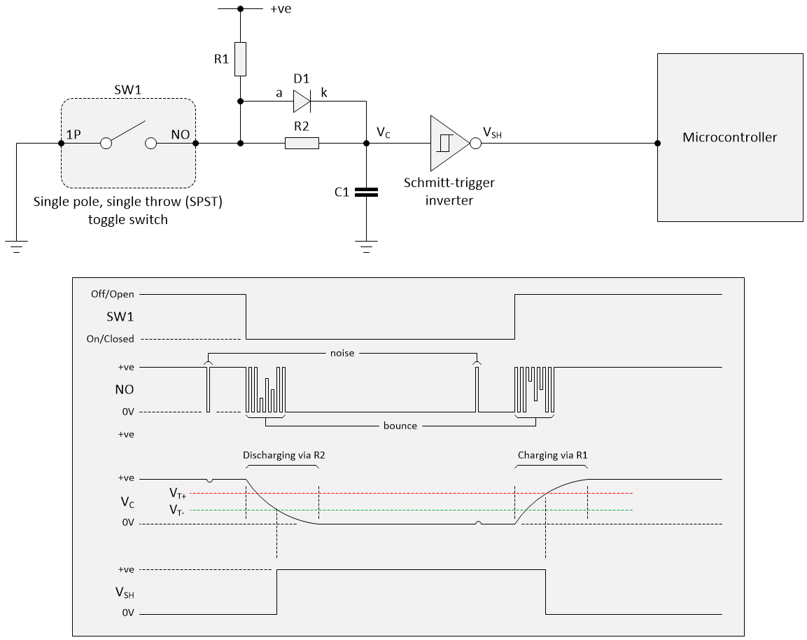
Debouncing a switch with an RC network, diode, and Schmitt-trigger inverter (Image source: Max Maxfield)
Actually, I have made a slight modification from our original version in that I’ve swapped the non-inverting Schmitt-trigger buffer to its inverting counterpart, which is slightly faster. If the truth be told, we’re only talking about a difference of a few nanoseconds, which is absolutely negligible in the context of our 20 ms RC delay, but this is the way I would do it if I had a choice (can you spell “Obsessive Compulsive”?).
Of course, this means that when the switch closes, the signal as seen by the microcontroller now goes from a 0 to a 1 (it used to go from a 1 to a 0); contra wise, when the switch opens, the signal as seen by the microcontroller now goes from a 1 to a 0 (it used to go from a 0 to a 1). Happily, this is trivial to deal with in software.
But we digress… the question posed by the reader involved the necessity of using diode D1. As we previously discussed, when we include this diode, our capacitor discharges via resistor R2 and charges via resistor R1. This allows us to individually specify the discharge and charge times. If we were to omit diode D1, then the capacitor would still discharge via R2, but it would charge via R1 + R2, which would make the switch’s deactivation delay longer than its activation delay.
Do we really care? If we’re talking about a human-machine interface, probably not, in which case we can omit the diode. On the other hand, if we’re talking about an application in which every millisecond counts, then adding the diode is the way to go.
This also leads us to think about the way in which we are using each toggle or pushbutton switch. For the purpose of these discussions, we’ll assume they both have normally open (NO) terminals. In the case of the toggle switch, it may be that activating (closing) the switch triggers some action in which we are interested delay-wise, but deactivating (opening) the switch is of less import. Alternatively, the actions of closing and opening the switch may each trigger some form of time-dependent activity.
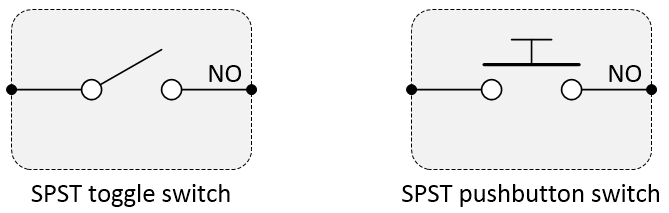
Symbols for SPST toggle and pushbutton switches (Image source: Max Maxfield)
When it comes to pushbutton switches, there are two main variants: latching and momentary. In the case of a latching pushbutton, we press it once to activate the switch and then press it a second time to deactivate it. As for the toggle switch, it may be that we are interested only in the activation delay, or that we are interested in both the activation and deactivation delays.
When it comes to a momentary pushbutton, pressing the pushbutton closes the switch, while releasing the pushbutton opens the switch again. It may be that simply pressing (and subsequently releasing) the switch triggers a sequence of activities, in which case only the activation delay will be of interest. Alternatively, it may be that we press the button to commence an activity, hold the button to continue the activity, and release the button to terminate the activity, in which case both the activation and deactivation delays may demand our attention.
Once again, all of this is application dependent. If we are talking about a relatively slow human-machine interface like a beer dispenser, for example, in which we push the button to start the beer flowing, hold the button until our glass is full, and release the button to terminate the flow, then the difference between 20 ms and 100 ms on the deactivation cycle is negligible (actually, in the case of beer, the fact that the flow takes even a little longer to turn off may be considered to be an advantage in certain circles). By comparison, applications in which the state of the pushbutton is dictated by the position of a mechanical mechanism may be more time dependent.
Traditional Hardware Debounce: Monostable Multivibrators
Another approach some people tout as offering a solution to switch bounce is to use a monostable multivibrator, or “one shot.” When triggered, this outputs a single pulse with a pre-defined duration. The circuit then returns to its stable state and produces no more output until triggered again.
Is using monostables to debounce switches a good idea? The short answer is “no,” while a slightly longer answer is “Heck no!” You could stop reading right now and wait for Part 5 of this miniseries, but if you insist…
The way a monostable is usually presented at a high-level of abstraction — and ignoring switch bounce — is as shown below:
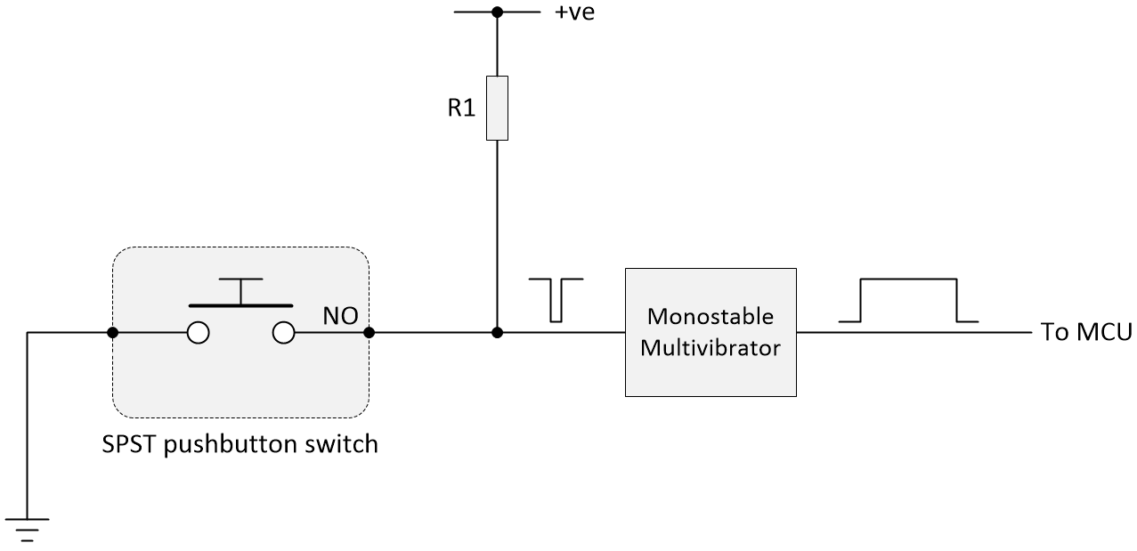
High-level view of monostable multivibrator (ignoring switch bounce) (Image source: Max Maxfield)
Of course, we know that our switch is almost certainly going to bounce, which means a stream of pulses will be fed into the monostable. The idea is that it’s the leading edge of the first pulse that triggers the monostable, whose output pulse commences almost instantaneously (after a few nanoseconds). So long as the width of the output pulse is sufficiently large (we’re assuming 20 ms) and the switch bounce terminates before this time, everything is hunky-dory, right? Well…
Let’s start with the low-hanging fruit. One switch debouncing circuit roaming wild and free on the internet is based on a monostable created using an N-channel MOSFET as illustrated below (we’re using the Rx annotation on the output resistor because we don’t want to confuse things with our earlier circuits).
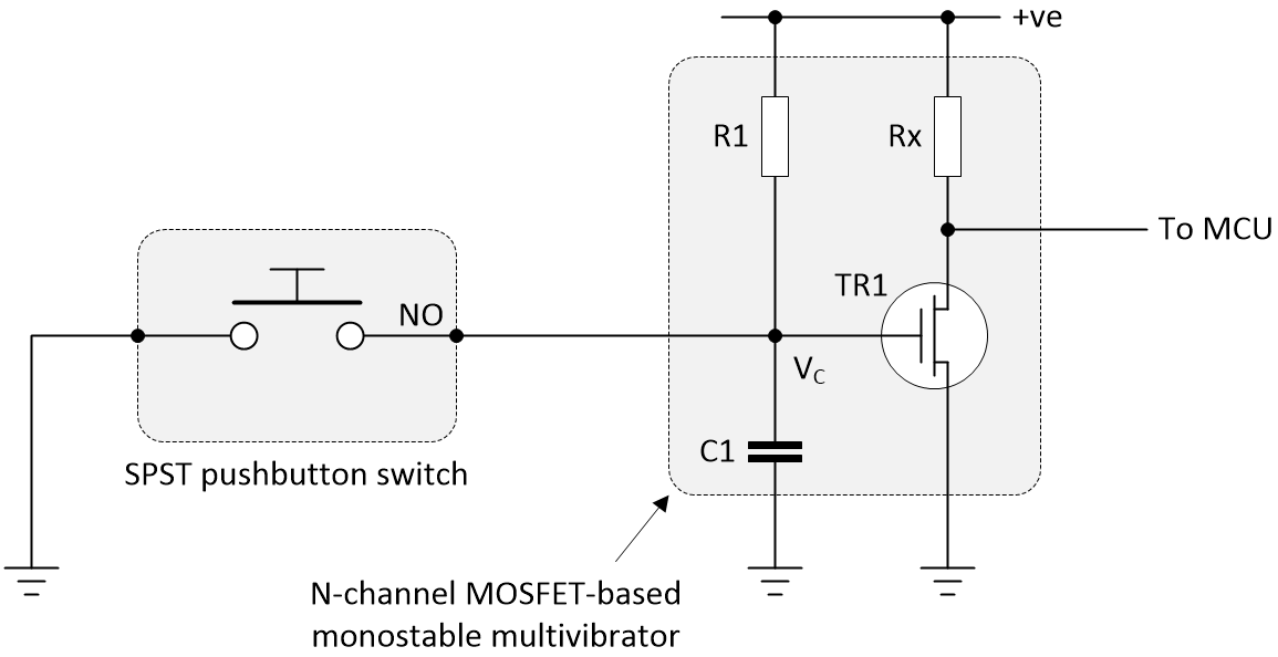
Really bad switch debounce circuit using an N-channel MOSFET-based monostable multivibrator (Image source: Max Maxfield)
Let’s we assume that our microcontroller is an Arduino Uno (because that’s what’s on my desk), which means we have a 5 V supply. The way we may assume that this circuit is supposed to work is as follows. Suppose we start with the switch open and the capacitor charged via R1 to 5 V, which turns TRI on, which means the microcontroller is presented with logic 0.
The way this is intended to function is that, when the switch is closed, the capacitor immediately discharges through the switch, which turns the transistor off, so the microcontroller now sees a logic 1. This situation will persist as long as the switch is closed. When the switch is opened, the capacitor starts to charge with the RC time constant defined by R1 and C1, eventually returning the signal being presented to the microcontroller to a logic 1.
In reality, there are so many things wrong with this circuit that it makes one’s eyes water. Let’s start with the fact that a lot of switches are rated for relatively low current values, such as 20, 25, 50, or 100 mA. I just checked one of the toggle switches in my spares box. When closed, this switch — along with a few inches of 24 AWG copper wire — had a total resistance of 0.2Ω. This means that the act of closing the switch will result in a surge current of 5V / 0.2Ω = 25 amps (eeek).
There’s also the fact that, when the capacitor is charging, the transistor will turn on gradually, which means the signal to the microcontroller will gradually transition from a logic 1 to a logic 0, but the microcontroller much prefers to be presented with crisp, clean 0s and 1s.
The bottom line is that we’re going to have to add another resistor through which the capacitor can discharge. We’re also going to have to add a Schmitt-triggered buffer or inverter on the output to sharpen up the signal being fed to the microcontroller. By the time we’ve finished, we’ll end up with a circuit looking something like the following:
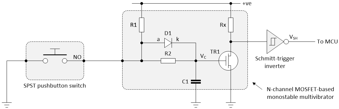
Still bad switch debounce circuit using an N-channel MOSFET-based monostable multivibrator (Image source: Max Maxfield)
Basically, we’re back to our original RC debounce circuit. The only thing that’s different is that we’ve now added an N-channel MOSFET inverter into the mix, which makes this a pretty pointless exercise.
I’ll cut this short because we could go on for hours. There are all sorts of monostable multivibrator circuits out there, many of which are awesomely great at what they do, so long as what we ask them to do does not involve debouncing switches.
For example, there’s the 74121 monostable multivibrator with Schmitt-trigger inputs, the 74122 re-triggerable monostable multivibrator, and the 74123 dual re-triggerable monostable multivibrator, all of which support both positive- and negative-edge triggers. Furthermore, if you root around the internet, you can also find multiple examples where people say you can take a 555 timer, configure it to act as a monostable, and use this to debounce your switches.
Sad to relate, all these monostable-based solutions have a fatal flaw. Let’s start by looking at the following signals that are often shown as part of these solutions:
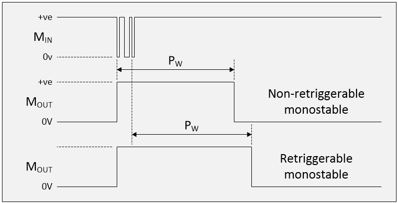
Unrealistic waveforms that are typically used to illustrate a monostable multivibrator switch debounce solution (Image source: Max Maxfield)
As we see, the initial falling edge on the monostable multivibrator’s input (Min) triggers the start of the pulse on its output (Mout). In the case of a non-re-triggerable monostable like the 74121, the width of the pulse (Pw) on the output is whatever we’ve defined it to be using appropriate resistors and capacitors (we’ll assume we’ve set this to 20 ms as discussed earlier in this column). By comparison, a re-triggerable monostable like the 74122 will be re-triggered on every bounce of the switch, thereby “stretching” the pulse on the output, because the delay Pw doesn’t commence until the last triggering switch bounce edge.
Take another look at the previous diagram. Can you spot the obvious flaw? The problem is that whoever created the original version of this diagram started with the switch in its inactive state, showed a few bounces, and immediately returned the switch to its inactive state, but that’s not the way things work.
What we should be showing is the switch starting in its inactive state, followed by bouncing, followed by the switch being in its active state, and this active state persisting until long (relatively speaking) after the end of the Pw output pulse. So, assuming a regular non-re-triggerable monostable multivibrator, what we’re actually going to see is the following:
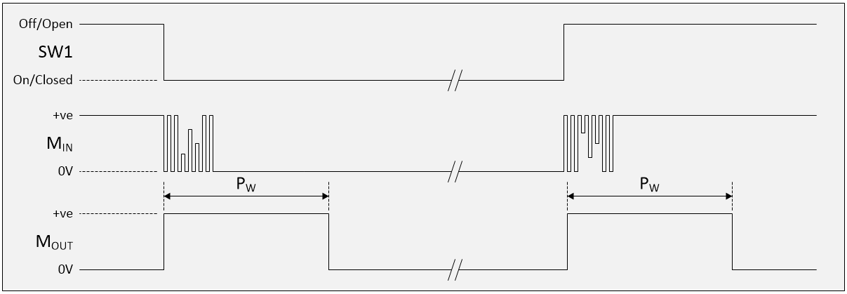
Realistic waveforms associated with a monostable multivibrator switch debounce solution (Image source: Max Maxfield)
Well, this is a fine kettle of fish, as they say. Consider the view from the point of the microcontroller, which will see a pulse every time you change the state of your toggle or pushbutton switch. In rare cases, this may be just what you are looking for, but most of the time — when all you want to know is whether the switch is open or closed — it will be a pain in the nether regions.
Believe it or not, things get worse. In Part 2 of this miniseries we introduced the topic of noise, and we noted that whatever switch debounce technique we adopt should not be fooled by the occasional “glitch” or “spike” caused by crosstalk, EMI, (electromagnetic interference), RFI (radio frequency interference), or ESD (electrostatic discharge). The problem is that the monostable will immediately trigger on any active edge on its input, even if that edge is part of a single, narrow, ESD pulse, for example (sad face).
One way around a lot of these problems is to use the falling edge at the end of the output pulse from the monostable to drive the clock on a D-type flip-flop; also, to use the output from the switch as the data input to the flip-flop as illustrated below:
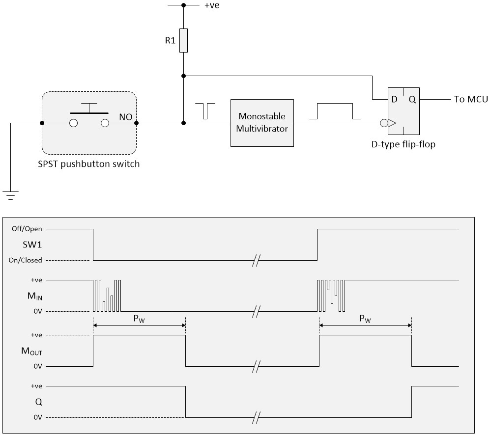
Functional monostable multivibrator switch debounce solution (Image source: Max Maxfield)
So, finally, we’ve achieved a switch bounce solution based on a monostable multivibrator that actually does what we want it to. On the one hand we might shout “Hurray!” On the other hand…
Is it just me, or have we made things overly complex? If we take a step back and think about things, all we’ve really achieved using our monostable multivibrator and D-type flip-flop is the same result we get using an RC delay and Schmitt-triggered inverter.
The bottom line is that I would be hard pushed to come up with a reason to implement a switch debounce solution based on a monostable multivibrator.
Next Time…
Believe it or not, when I first started writing about this topic, I thought I could do it in just one or two columns, but there’s still so much to cover. Next time we’ll be looking at… but no… let’s keep that as a surprise. In the meantime, as always, I welcome your comments, questions, and suggestions.


just an addendum to your comment “The bottom line is that I would be hard pushed to come up with a reason to implement a switch debounce solution based on a monostable multivibrator.”
In my very early days I was implementing a 16 switch keypad to binary- the hex keypad had 16 switches with a common pole. The solution (from a Motorola app note, if I recall correctly) was to use 2x MC14532 8-bit priority encoders( http://www.ti.com/lit/ds/symlink/cd4532b.pdf) ; OR the GS output from each 4532 and then use the OR output to clock a monostable (I think it was the MC14528), thus allowing one debounce circuit for all 16 switches. As I recall the Qn outputs were also ORed. (That might have been easier to explain just using 8 switches). just sayin’ that only one debounce circuit could be a justification when the MC14490 (https://www.onsemi.com/pub/Collateral/MC14490-D.PDF) didn’t yet exist…
Very interesting — thanks for sharing — in fact I’ll be talking about using an OR of multiple switches to trigger an interrupt later in the series — but it’s interesting to hear that someone successfully used a monostable in a switch debounce scenario
Max, I’m enjoying this series very much.
Debounce is one of those things you always will have in any project. In FPGAs, bouncing inputs can wreak havoc in your FSMs and find nasty bugs in your sequential logic.
Sometimes you have to group switches that are related (like multipole switches) and need to be latched all at the same time.
Such is the case in a circuit I shared a long time ago in OpenCores: https://opencores.org/projects/debouncer_vhdl
And it is still there getting downloads.
Awesome — thanks Jonny — I’m taking a break for a couple of weeks because some other topics are demanding my attention, but I’ll be coming back with Parts 5 and 6 soon and I’ll reference your FPGA solution then.
Hi Max,
I guess there can never be enough discussions about de-bouncing. To add my contribution to the naive questions…
Suppose we have a signal flow as below:
4 banks of 8 switches (24V )—> Optoisolation —-> Latch (74HC573 perhaps) —–> Port of uC (8051 perhaps)
Does it matter where the RC debouncing is applied ? Debouncing at the uC port would result in the fewest number of components,I guess.
I’m not ignoring you … I ‘m either (a) thinking or (b) asking friends who — unlike yours truly — actually have a clue LOL
EmbSysDev- In this case I don’t think it would be a good idea to debounce at the microcontroller as long as there is a latch between the optos and the micro. It could latch the wrong state. if the uC has Schmitt inputs, I’d leave out the latch and add a small capacitor across the LED in the optocoupler.
-Rick
I haven’t debounced a switch in hardware in more than 30 years. My designs always have a MCU of some sort in them and I’ve always had an available pin and processing time to implement a debounce routine. I vastly prefer that route, as I can change the algorithm as needed to suit the situation, without having to worry about it up-front. I do put ESD protection on switch inputs that need it, but that’s the extent of my use of hardware in the switch interface.
Thanks for your response — I’m taking a switch bounce break for a couple of weeks because some other topics are demanding my attention — but I’ll be back with more on this topic soon — when we get to the software solutions, I’ll be interested to hear your thoughts on the various approaches I present.
Given that the switch is a human interface and not something like a limit switch then I use no debounce hardware and no special software routine either. I simply read the switch value for instance every 20ms (must be longer than any expected bounce) and use whatever value I read.
If the switch state has just changed (let’s say it just closed) and so the read is within the bouncing then you might read either value.
If it read open then the next read will read the closed value 20ms later.
If it read as closed then that is the correct value as the button has just been closed.
So the bounce is completely ignored.
Where this system will fail is with a noise pulse if you happen to read during this pulse so if noise may be a problem then some system will be needed to eliminate responding to noise.
Hey Max,
So, so far we have been asking ourselves this question:
for how long after a press or a release does the switch exhibits bouncing?
Or rephrasing the question a little bit:
What is the longest time for which a switch exhibits bouncing after a press or release?
Now, I sugggest we look at the problem from a different perspective. For that purpose, I suggest inverting the question terms, becoming:
What is the shortest time for which a switch does NOT exhibit bouncing after a press or release?
Or, again, to put in different terms, how long does a switch takes to be considered stable after an event ocurred ?
This, independently of how long the bouncing takes. What we are really interested in finding out is if the bouncing has stopped.
Once we define that (let’s say, T=10ms, which is quite long) we can use the following technique, which is better implemented in software or a mix of software and hardware:
– Low-pass filter the “noise”. Just to avoid glitches.
– Define a switch state, either “stable” or “unstable”. Assume stable at reset.
– Define the switch output, either 0 or 1. Use the hardware default at rest. Let’s call this output “OUT”
– IF the switch is stable at “OUT” (either 0 or 1), then:
* If any event occurs on the switch, update outputs to NOT “OUT”, enter unstable mode. Start a timer which elapses at “T”
* If no events occur, keep “O” as is
– IF the switch is unstable, then:
* If no event has been observed for time T (i.e., timer elapsed), update “OUT” with current switch input.
* If any event occurred, restart the timer with time T.
What this does effectively is to ignore any event on the switch if the switch has not been stable for time “T”. It has several advantages, which are quick response, and relatively good immunity.
It can also be implemented on simple microcontrollers (such as PADAUK PMS150C-U6, which cost three cents (USD0.3) and has a nice SOT23-6 footprint).
Alvaro
Hi Alvaro — this is certainly one approach — to wait for a stable period following any bouncing BEFORE responding — but there’s also an argument to be made for responding immediately and THEN waiting for the bouncing and stable period before doing anything else. I’ll be talking about this in my next switch bouncing column (or maybe the one after that because we still have some interesting hardware solutions to peruse and ponder)
Hi Alvaro, the diode in the schmitt trigger input is not necessary due to the hysteresis threshold.
Please refer to the resistor calculation formula on https://www-mikrocontroller-net.translate.goog/articles/Entprellung?_x_tr_sl=auto&_x_tr_tl=en&_x_tr_hl=en-US&_x_tr_pto=wapp
Sorry for the mis-addressing. I did mean Max, not Alvaro. 🙁
Hi ejunkie — thanks for sharing — Max