

Way back in the mists of time, when I was bright-eyed and bushy-tailed, as I penned the first words in this quest to explore the topic of switch bounce and debounce, I actually thought it would take only one, perhaps two, columns. Sad to relate, as the days grew into weeks and the weeks grew into months, I grew into a much sadder and wiser man.
I can’t believe we’re now at Part 6. As I sit here at my kitchen table (see also Kevin’s Work from Home Survival Guide) gamely trying to out-stare my monitor, I fully expect this to be the last in the series, but I never know exactly what I’m going to write until the words start dripping off the end of my fingertips, where these chirpy and jaunty little beauties (the words, not my fingertips) are freshly picked at the crack of dawn on the north side of the hill while the morning dew still glistens on their pert and perky serifs, spurs, and tails. The bottom line is that we’ll all have to wait until we reach the end of this column to see if it truly is the end of the series. (“Dum dum dum duuuuuuum… Dum dum dum duuuuuuum…” The tension mounts.)
Before we plunge headfirst into the fray with gusto and abandon, let’s briefly remind ourselves how we reached this point in our deliberations. In Part 1, we introduced the concept of switch bounce. Later, in Part 2, we took a deeper dive into the bouncing associated with a single pole, single throw (SPST) toggle switch and a single pole, double throw (SPDT) toggle switch.
In Part 3, we started to consider hardware solutions to switch bounce, commencing with the idea of using an RC network followed by a Schmitt trigger to debounce an SPST toggle switch. In Part 4, we looked at using a variety of monostable multivibrators to debounce SPST toggle switches (unfortunately, we eventually concluded that using monostable multivibrators was not a good way to go).
Most recently, in Part 5, we returned to SPDT toggle switches and considered debounce techniques based on latches implemented using two inverters, SR latches (both NAND and NOR-based), and D-type latches and flip-flops.
In this column, we are poised to look at one remaining category of hardware-based debounce solutions in the form of special integrated circuits (ICs). If the fates smile upon us, we will also touch on implementing debounce in field-programmable gate array (FPGA) designs. Finally, we will turn our attention to software debounce techniques.
If any of this stuff is unfamiliar to you, then you might want to take a look at my associated Switch Types and Switch Terminology columns. You may also be interested in perusing and pondering my Registers vs. Latches vs. Flip-Flops column. Last, but certainly not least, as we’ve noted before, toggle switches, rocker switches, and pushbutton switches all exhibit switch bounce in pretty much the same way. In fact, the only switches that don’t bounce are the ones most of us rarely, if ever, use, such as mercury tilt switches.
Characterizing the System
Before we start to delve deep, and while I’m thinking about it, when I was chatting with embedded guru Jack Ganssle a few weeks ago, he mentioned that his recommendation to anyone involved in designing a system – especially folks designing mission-critical and safety-critical systems – is that they characterize the switches they plan on using before deploying them on an unsuspecting world.
It’s all too easy for both hardware designers and software developers to fall back on “tried and true” solutions without fully thinking things through. For example, in Part 1 of Jack’s classic Guide to Debouncing, he mentioned a type of switch that involved gold contacts plated onto a printed circuit board (PCB). There was an associated rubber cover that – when depressed – presented some sort of conductive elastomer to the gold contacts. Jack noted that the analog result was a slow ramp from zero to five volts, with no noise, wiping, or other uncertainty, and not a trace of bounce. Unfortunately, when this signal was presented to a TTL input, its slow ramp across the “forbidden zone” (0.8 to 2.0V) resulted in a millisecond (ms) of wild oscillations, which might be considered to be “virtual bounces.”
Dedicated Debounce Chips: On Semiconductor
In addition to jellybean logic chips containing SR latches – like the MC14043 quad NOR-based SR latch and MC14044 quad NAND-based SR latch from On Semiconductor – there are a few specially designed switch debounce chips on the market.
One such device is the MC14490 from On Semiconductor, which supports six channels (SPST switches), each of which employs a 4-bit shift register. This device requires a clock for its operation. The clock may be derived from an internal RC oscillator, which requires an external capacitor to adjust for the desired operating frequency (bounce delay). Alternatively, the clock may be driven from an external source, including the oscillator from another MC14490.
Dedicated Debounce Chips: Maxim Integrated
Another option is to use one of Maxim Integrated’s MAX6816/MAX6817/MAX6818 devices, which support one, two, and eight channels, respectively, where each channel employs an internal counter. These devices remove bounce when a switch opens or closes by requiring the signal from the switch to remain in the same state for a number of sampling periods. The output does not change until the input has been stable for 40 ms. One issue is that these chips are available only as surface-mount devices (SMDs), but many hobbyists – and even prototyping professionals – enjoy having access to components with lead-through hole (LTH) packages.
As an aside, when we come to consider software solutions to the switch bounce problem, one such solution involves a shift register technique, while another employs a counter-based approach. The reason I mention this here is that we see both of these methods implemented in hardware in the aforementioned devices.
Dedicated Debounce Chips: Texas Instruments
To be honest, you never know what’s lurking around the corner. As an example, following an earlier column, my chum Jack Grubbs emailed me to say, “Hi Max, I’m really enjoying this series of articles on switch debouncing.”
Well, this immediately put me in a good mood, and we were obviously off to a good start with regard to our email exchange. Jack went on to say, “The TIC12400-Q1 from Texas Instruments (TI) is an automotive-grade device that can monitor 24 switches with configurable wetting current settings. It’s also got an integrated 10-bit analog-to-digital converter (ADC) for use with multi-position analog switches, along with an integrated comparator with four programmable thresholds for digital switch monitoring. They also have a $199 Evaluation Module Kit, along with a User Guide for said evaluation kit. The biggest downside to this device is that its data sheet is 135 pages long!”
Dedicated Debounce Chips: LogiSwitch
Before we proceed, I have to admit that I’m somewhat biased here, because I currently use the switch debounce chips from LogiSwitch in all of my projects. As an aside, the founder of LogiSwitch, my chum Mike Pelkey, is the grandfather of BASE Jumping; i.e., parachuting from a fixed structure, where BASE is an acronym for building, antenna, span (bridge), and earth (cliff). Along with his friend, Brian Schubert, Mike made the first parachute jumps from the top of the El Capitan mountain in Yosemite National Park in 1966. But we digress…
Throughout more than 40 years of designing digital systems, Mike – like almost every other hardware designer engineer on the planet – was plagued by the switch bounce problem. Having employed virtually every version of traditional hardware-based and software-based switch bounce mitigation techniques known to humankind, Mike decided that there had to be a better way.
The result of Mike’s cogitations and ruminations was the LogiSwitch concept. Boasting adaptive bounce detection algorithms and (in the case of the LS1xx series) a unique 1-wire handshaking protocol, these bodacious beauties reflect the current state-of-the-art in switch bounce mitigation technology.
Let’s start with the high-noise immunity LS18/LS19/LS20 chips, which can handle 3, 6, and 9 channels, respectively. Happily, for me, all of these devices are available in both SMT and LTH packages. Consider the following circuit using an LS18:
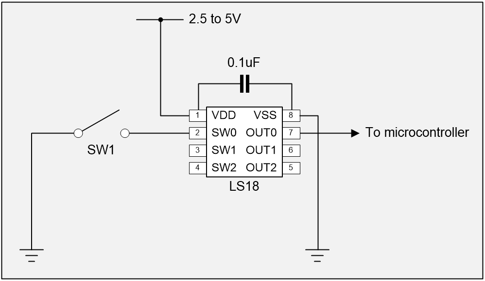
The LogiSwitch LS18 in a circuit (Image source: Max Maxfield)
Observe that we don’t need any pull-up resistors on the inputs to (or the outputs from) the LS18, because this chip handles all of this internally. The 0.1 uF decoupling capacitor is optional, but it provides increased immunity to noise. We’re just showing a single SPST switch here, but the LS18 can accommodate three such switches. Now consider a typical switch bounce scenario as illustrated below:
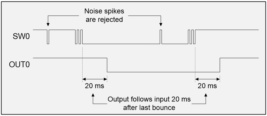
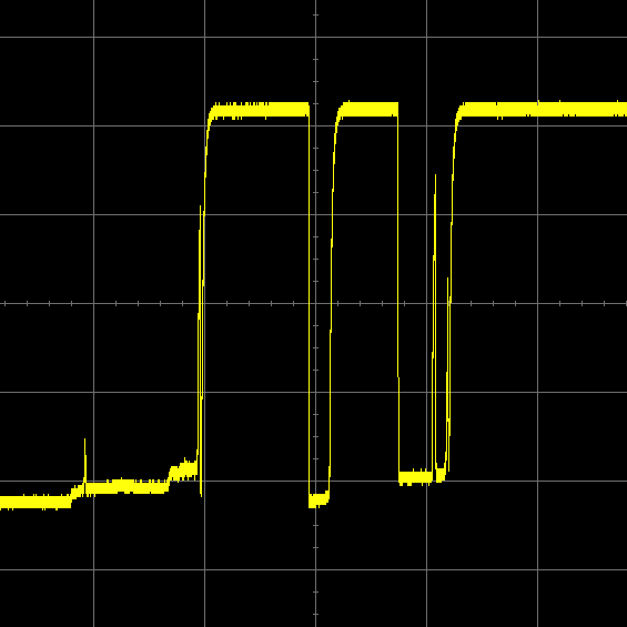
LogicSwitch LS18 reacting to noise and switch bounce (Image source: Max Maxfield)
As we see, the LS18 rejects any noise spikes. In the case of an actual switch transition, the LS18’s output will follow the input from the switch 20 ms following the last switch bounce.
Now let’s look at the fast-response LS118/LS119/LS120 chips. Once again, these can handle 3, 6, and 9 channels, respectively. And, once again, all of these devices are available in both SMT and LTH packages. Let’s begin by considering a typical switch bounce scenario with an LS118 chip as illustrated below:
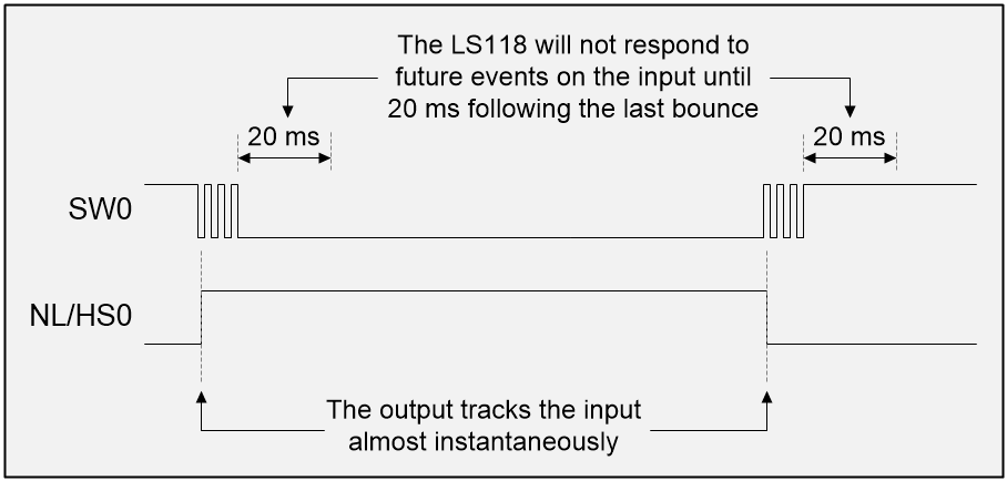
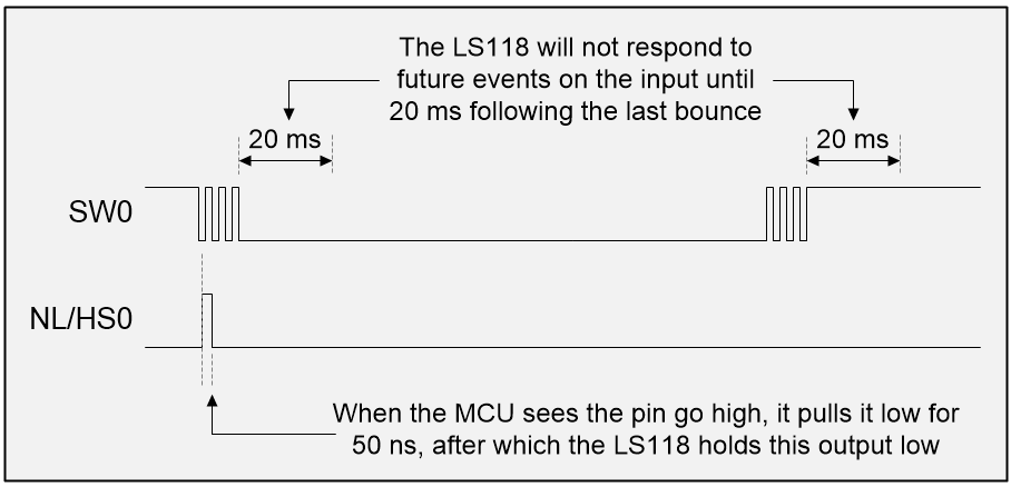
LogicSwitch LS118 chip reacting to switch bounce but without using its handshake capability (Image source: Max Maxfield)
Observe that the “normally low/handshake” (NL/HS) output is the opposite phase to the switch input; that is, when the switch is connected to 0 V (logic 0), the NL/HS output will be logic 1, and vice versa.
The NL portion of this pin’s moniker is based on the assumption that we are dealing with an SPST switch whose “normally open” (NO) contact is pulled-up to logic 1 (once again, the LS118 chip handles the pull-up resistors internally). So, when the switch is inactive (logic 1), the NL/HS output is logic 0.
There are two important things to note here. First, following a transition on the switch, the NL/HS output responds almost immediately (within a matter of nanoseconds). Second, the LS118 will not respond to any subsequent events on the input until 20 ms following the last switch bounce.
Now, sit up and pay attention, because this is where things start to get very interesting. The LS118/119/120 chips boast a unique 1-wire handshaking protocol. When the microcontroller (MCU) “sees” one of the NL/HS signals go high, it can change that input pin into an output, pull the signal low for 50 microseconds (µs), and then return the pin to being an input.
The outputs from the LS118 are open collector with internal pull-ups. When the LS118 sees that the MCU is pulling one of its outputs low, it starts to drive that output low itself. The result is as illustrated below:
LogicSwitch LS118 chip reacting to switch bounce and using its handshake capability (Image source: Max Maxfield)
This handshake capability is of interest for a number of reasons. For example, consider a program that loops around checking the state of a switch and performing some action like, “If the NL/HS signal is 1, then add one to the counter.”
Without our handshake capability, the programmer has to set a flag to keep track of when the switch has been activated to ensure the program doesn’t keep on incrementing the counter. This isn’t rocket science, but it’s one more thing to worry about. By comparison, using the handshake makes life much simpler. In our example, when the MCU sees the NL/HS go high, all it has to do is increment the counter and clear the NL/HS signal back to 0, and that’s it until the signal goes high again.
But this is just the start. Armed with this handshake protocol, we can… but no! I’m sorry, but this column is already much longer than I had intended, so we will have to wait for…
Next Time
In my next column, we will conclude our discussions on the various usage scenarios associated with the LS1xx handshake protocol, we will consider the use of switches with reset inputs and switches with interrupts, we will ponder how to handle switch debounce in FPGAs, and – finally – we will immerse ourselves in software solutions to the switch debounce problem.
I promise that my next switch bounce column will be the last in this mini-series (no, of course I don’t have my fingers crossed behind my back when I say this; how could you possibly suggest such a thing?). Until next time, as always, I welcome your comments, questions, and suggestions.


This entire series of articles has confused me. It reads to me more as a historical piece than as a practical guide for future designs. All (or nearly all) of the discrete hardware solutions cost more than software debounce on a low-cost microcontroller. I just priced a the MC 14490 hex contact bounce eliminator (which only eliminates bounce in those applications that fall within its limited abilities) and see that it’s about the same price as a 32-bit ARM MCU in a 64 pin package, around $3.50 at Digi-Key.
Devices like the TIC-12400 handle a heck of a lot more than debounce (high ESD, contact wetting, serial interface, etc) and may make economic sense. As I think I mentioned in a comment to a previous episode of this series, I haven’t used a dedicated hardware debounce circuit in perhaps 40 years.
Jack Gannsle is correct in recommending characterization of the debounce before designing a method to address it, but there are situations in which you don’t/can’t model the switch completely until late in the game . Putting the debounce solution in software allows that.
A 74HC14 hex Schmitt trigger costs a dime. An ATtiny13A MCU in a 20 pin package is $0.35. There is a programming cost associated with the latter, but there’s a very good chance I’ll already have need for something like that part elsewhere in the design.
Surely most modern embedded systems already employ some sort of MCU to provide other functions, as has been true of every single thing I’ve designed since entering the engineering workforce in 1976. I have never done switch debounce in hardware… never.
It’s certainly worthwhile for young engineers to understand the complex nature of switch debounce, but it really does seem to ignore the economics of modern embedded design.
I wouldn’t argue that debouncing in software is an excellent choice for high-volume production projects. Debouncing in hardware may be more appropriate for smaller projects and hobbyists. Having said this, there must be a reason why well-known devices like the MC14490 from On Semiconductor and the MAX6816 / 6817 / 6818 from Maxim Integrated are available from component distributors like Arrow and Digi-Key, who don’t tend to offer components that aren’t selling.
Also, I think your pricing is low — I think these chips are around $5+ in 1-off quantities — the $3+ price is if you but them in 1,000 quantities.
FYI, the price of a LogiSwitch 3-channel LS18 in a SOIC 8-pin surface mount package is $2.99 in 1-off quantities.
But again, I wouldn’t argue with you that software is the way to go in the majority of cases in high-volume production products.
So, why have I spend so much time discussing hardware solutions (we will get to the software solutions soon, I promise). One reason is that I’m a hardware design engineer by trade. I can write software at a basic level, but you certainly wouldn’t want me coding for your medical devices or military systems. Another reason is that I love the history of this stuff — the fact that we used to do it all in hardware, and that we now do it (mostly) in software. Yet another is that I love teaching people about fundamental concepts like switch bounce. And one more reason is that there are so many articles on switch bounce out there that either get things wrong, or that only cover parts of the picture. The purpose of this series is to gather everything together in one place so that newcomers to the profession in years to come will be able to use this series as a “one-stop-shop”.
Oooh, Oooh — I just thought of one more reason — I’m proud of my diagrams, but it’s hard to draw a diagram of a piece of software (although I’m going to give it “the old college try” when we get to look at software solutions 🙂
I’m certainly all for teaching about switch bounce, as it’s not obvious to the uninitiated that it actually occurs. I’m also all for teaching about understanding the required response time for any function driven by a switch (or any other signal for that matter). The correct method for debouncing must understand both ends of the problem.
The MC14490 is an “ancient” part, probably still for sale because there are old designs still using them. They were considerably cheaper 30 years ago than they are now. I think that reflects their declining usage.
It’s harder for me to explain the attraction of the MAX6816-18 family. Those are expensive devices ($1.3-7+) and, outside of their 15KV ESD protection don’t do anything that can’t be easily done in the MCU. For very low volume or hobby work it might be a good solution, but once you’ve debounced a switch in firmware it’s not hard to bring the code forward into new designs.
The one place I’d consider using hardware is in keyboard/pad sensing. The TI TCA8418E has 15K ESD and handles up to 80 switches. It’s got a serial (I2C) interface and is $0.58@1K. That’s pretty good bang for the buck. That part can probably handle no more than 2 closed switches at a time.
In many of my real time designs, switch inputs were just another noisy signal that had to be software filtered before entering the system logic. I’ve even used spare channels of A/D to digitize the switch voltage, passing it through the same filtering as true analog signals.
As someone who never trusts himself to fully understand the problem until it’s “too late”. I’ve always favored solutions that could be modified right up to “the last minute”.
As I’ve said before, I’m a hardware design engineer by trade, so I guess hardware solutions hold a certain appeal for me. It’s like the old saying goes, “If your only tool is a hammer, everything starts to look like a nail” 🙂
I will be interested to hear your thoughts on my next column where I cover software solutions to the switch bounce problem. Just try to be kind, remembering that I’m making all of this up as I go along LOL