

I love learning how logic designers of the past solved tricky problems with innovative solutions. The more I delve into this sort of thing, the more I say to myself, “Wow! I would never have thought of that!” A great example is binary coded decimal (BCD) because there’s a lot more to this topic than one might, at first, suppose.
In fact, may I make so bold as to say that, even if you’re a digital logic guru boasting a size-16 brain with go-faster stripes on the sides, if you don’t learn something new in this column then my name isn’t Max the Magnificent!
Speaking of logic, before we dive headfirst into the BCD fray with gusto and abandon (and aplomb, of course), let’s take a moment to remind ourselves of one of my favorite logical conundrums.
We start with a black box that has three inputs, A, B, and C, along with three outputs NotA, NotB, and NotC. The three outputs are the logical inversions of their corresponding inputs (when A is 0, NotA is 1; when A is 1, NotA is 0; when B is 0, NotB is 1… etc.).

Our task is to specify the contents of the black box. If we were permitted to use any logic gates we desired, then we would need only three NOT gates to do the job. Sad to relate, there’s a problem in that we are informed we have only two NOT gates at our disposal. Also, before you ask, we aren’t allowed to use any NAND, NOR, XOR, or XNOR gates. On the bright side, we can use as many AND and OR gates as our hearts desire.
If you haven’t been exposed to this little scamp before, then it’s well worth your taking the time to ponder this poser. Although it may appear impossible at first, there really is a no-trick logical solution, which is presented at the end of this column for your delectation and delight.
Setting the Scene
As I mentioned in an earlier article (Arduino 0s and 1s, LOW and HIGH, False and True, and Other Stuff), I’m currently in the process of penning a series of Arduino Bootcamp columns for Practical Electronics (PE), which is the UK’s premier electronics and computing hobbyist magazine.
Unfortunately, the editor of that glorious tome, the nefarious illustrious Matt Pulzer, wants me to focus on nitty-gritty hands-on stuff. Matt is fiercely fighting my wandering off into the weeds as is my wont, so—since I can’t cover everything on PE’s printed pages—I’m writing ancillary articles like this to capture and share a lot of super-interesting contextual material (take a look at my Solderless Breadboard Blog, for example).
The early columns in my Arduino Bootcamp series describe myriad ways to employ 7-segment displays, including multiple manifestations of BCD. As part of this, I’m creating what I consider to be some super-spiffy diagrams, an example of which is shown below.
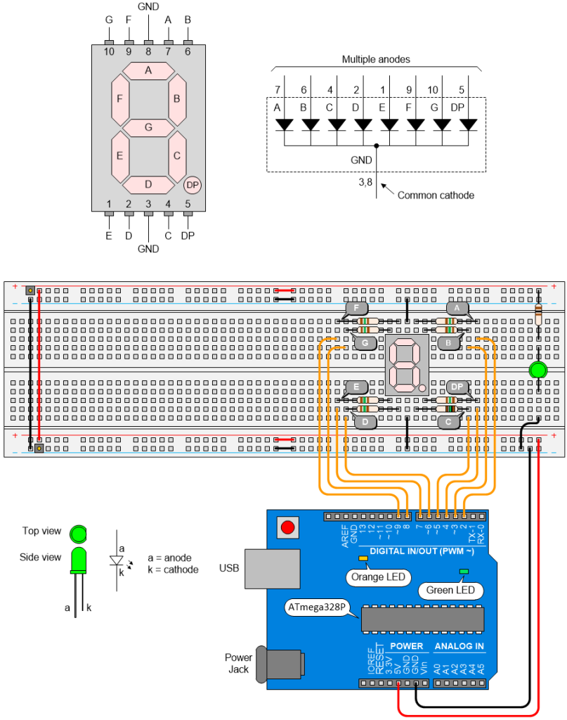
Feast your orbs on my awesome diagrams (Source: Max Maxfield)
The reason for the jumper wires in the middle of the power and ground rails at the top and bottom of the breadboard is discussed in the aforementioned blog.
What’s that? Do I hear you muttering “I bet these images are created using Fritzing Software” under your breath? If so, you’d lose your money because I create all my diagrams using Microsoft Visio. Like many engineers, I have a hint of a sniff of a whiff of the obsessive-compulsive about me. As a result, over the years, I’ve spent countless happy hours handcrafting artisanal diagrams of this ilk.
How Many Fingers?
As we discussed in our 0s and 1s column, the underlying foundation for the overwhelming majority of today’s digital computers is the binary (base-2) number system, which supports only two values: 0 and 1.
The reason for using binary is that it’s relatively easy for us to create electronic implementations of simple logic functions like AND, NAND, OR, NOR, XOR, and XNOR that can detect the difference between two different voltages on their inputs and generate those voltages on their outputs.
Rather than talk in terms of specific voltage values, we abstract them and refer to them as 0 and 1. In addition to considering these 0 and 1 values to be binary numbers, we can also use them to represent the Boolean concepts of false and true.
A single binary digit is called a bit. We can gather groups of bits together to represent pretty much anything we want, including numerical values in the form of integers or floating-point numbers, alphanumeric characters and punctuation symbols, and… the list goes on. Two very commonly used groupings are 4-bit nybbles (or nibbles) and 8-bit bytes.
Unfortunately, humans find it difficult to think in terms of binary numbers. As a result of our having ten fingers (including thumbs), the number system with which we are most familiar is decimal, a.k.a. denary (base-10), which employs ten digits: 0, 1, 2, 3, 4, 5, 6, 7, 8, and 9. For a variety of reasons, including extensive usage, we tend to find decimal intuitive to use and easy to understand. For example, if you happen to find yourself wandering around an abandoned mansion in the middle of a dark and stormy night, and you hear eldritch sounds emanating from a room with the binary number 001010011010 daubed on the door in (what one can only hope is) dripping red paint, you may not have the same visceral reaction as you would if the same value were presented in decimal as 666 (I fear I’ve seen more horror films than is good for me).
As an aside, the term tetrapod refers to an animal that has four limbs, along with hips and shoulders and fingers and toes. The superclass Tetrapoda includes humans and hippopotami, amphibians and aardvarks, frogs and crocodiles, sauropsids and synapsids, and… once again, the list goes on. The most primitive tetrapod discovered thus far is Acanthostega, which appeared in the late Devonian period (Famennian age) about 365 million years ago. The reason I mention this here is that Acanthostega had eight fully developed fingers on each hand.

The first tetrapod, Acanthostega, had eight fully developed fingers on each hand
(Source: Max Maxfield and Alvin Brown)
If evolution hadn’t taken a slight detour, we would probably have ended up using a base-16 numbering system, which would have been jolly handy (no pun intended) when we finally got around to inventing digital computers, but we digress…
Dipping Our Toes in the BCD Waters
To summarize where we’re at thus far: (a) humans prefer to play with decimal representations and (b) digital computers are happiest when working in binary. What we need is some way to map (translate) between the two. In fact, there are myriad mapping possibilities, and it is this class of binary encodings of decimal numbers that we collectively call binary coded decimal (BCD).
Since four bits can represent 24 = 2 x 2 x 2 x 2 = 16 different combinations of 0s and 1s, it takes only four bits to encode our ten decimal values.
The most intuitive and obvious form of BCD is based on using the natural binary number scheme (“natural” because it follows the general counting method employed in decimal and other place value numbering systems). In this case, which most people typically think of as epitomizing BCD, but which should more properly be referred to as natural BCD (NBCD) or simple BCD (SBCD), each digit has a weight associated with it. As we discussed in our 0s and 1s column, these weights are 23, 22, 21, and 20, which equate to 8, 4, 2, and 1, so this approach is also known as “8421 Encoding” or “BCD 8421.”
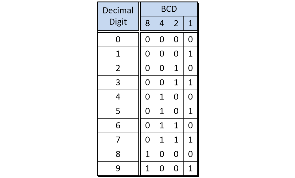
BCD 8421 (Source: Max Maxfield)
Observe that there are six unused binary combinations in a 4-bit nybble used to store a BCD digit. In the case of BCD 8421, these unused combinations are 1010, 1011, 1100, 1101, 1110, and 1111.
Although this isn’t something I’ve ever run across in the real world myself, a nybble holding BCD values may be referred to as a tetrade (from “a group or set of four”), in which case the ten states representing the BCD digit may be referred to as tetrades or tetrads.
Packed and Unpacked
Most computers deal with data in the form of 8-bit bytes. Even in the case of machines with 16-bit, 32-bit, and 64-bit data paths, we tend to think of these paths as being 2, 4, and 8 bytes wide, respectively.
Bearing this in mind, it’s possible to encode BCD 8421 values in one of two ways: unpacked or packed. In the case of unpacked BCD, each BCD digit is encoded into the four least-significant bits (LSBs) (bits 0 to 3) of an 8-bit byte, while the four most-significant bits (MSBs) (bits 4 to 7) of that byte have no significance (they are typically loaded with 0s). In this case, the decimal value of 95 would be encoded as shown below.
Storing a decimal value of 95 as unpacked BCD 8421 (Source: Max Maxfield)
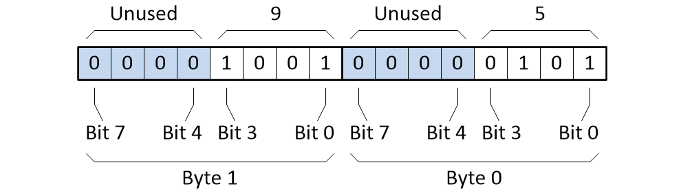
By comparison, in the case of packed BCD, two BCD digits are encoded into a single byte, with one digit in the least-significant nybble (LSN) (bits 0 to 3) and the other digit in the most-significant nybble (MSN) (bits 4 to 7). In this case, assuming a big-endian format, the decimal value of 95 would be encoded as shown below.
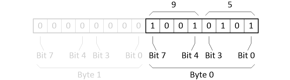
Storing a decimal value of 95 as packed BCD 8421 (Source: Max Maxfield)
Shifting and masking operations can be used used to pack or unpack BCD digits (see also my column Masking and the C/C++ Bitwise Operators).
Input and Output
“This is all very interesting, but is BCD still used today?” I hear you cry. You can bet your little cotton socks it is! We will talk more about this later but—as a tempting taster—one common application is allowing humans to easily specify decimal values using BCD thumbwheel switches, such as the 302109000 from C&K (now part of Littelfuse).
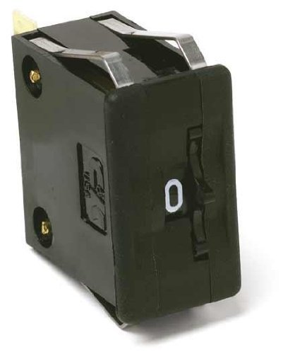
A 302109000 BCD thumbwheel switch (Source: C&K)
In this case, the operator rotates the thumbwheel on the front, and the corresponding BCD code is presented on four terminals at the rear. Commonly employed in industrial control applications, groups of these switches can be mounted together, thereby allowing users to specify larger numerical values.
Another common application is to present decimal values on 7-segment displays. In the case of a single-digit common cathode 7-segment display, for example, we could use a CD4511 BCD-to-7-segment decoder from Texas Instruments. A simplified representation of the CD4511’s truth table is illustrated below.
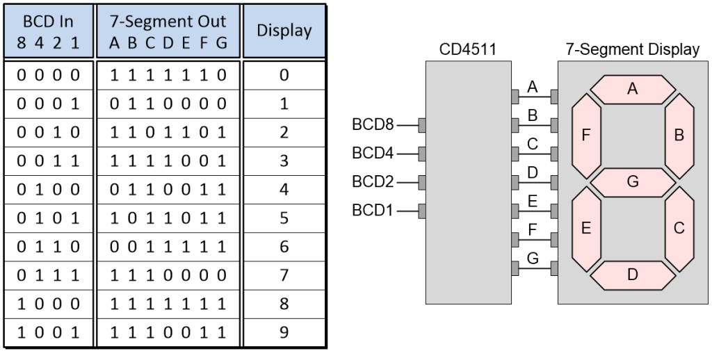
CD4511 BCD-to-7-segment decoder truth table (Source: Max Maxfield)
The reason we say this is a simplified version of the truth table is that the CD4511 also has Lamp Test (LT), Blanking (BL), and Latch Enable (LE) inputs that can be used to test the display, shut off or modulate its intensity, and latch/store a BCD code, respectively.
Unsigned, Sign-Magnitude, and Signed Binary Numbers
Later on, we’re going to look at different ways of representing large numbers formed from BCD digits. Before we do so, however, it might be a good idea to quickly refresh our minds as to how we do things in binary.
To keep things simple, let’s work with 4-bit binary values. As we know, four bits can represent 24 = 2 x 2 x 2 x 2 = 16 different combinations of 0s and 1s. If we decide to use these combinations to represent only positive values (we call this unsigned binary), then we can represent the decimal values 0 to 15. This is shown as (a) in the diagram below.
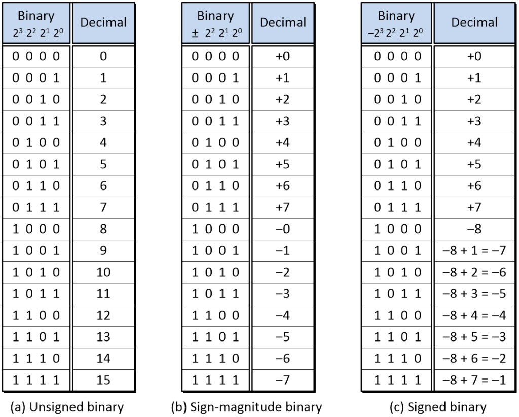
Comparison of unsigned, sign-magnitude, and signed 4-bit binary numbers (Source: Max Maxfield)
If we wish to represent both positive and negative numbers, then there are two commonly used approaches. The first, whose usage is relatively rare, is called sign-magnitude binary. This is shown as (b) in the diagram above. In this case, the most-significant bit (MSB), which is called the sign bit, is used to indicate positive and negative values (0 = positive, 1 = negative). The remaining bits, which have the same column weights as before, are used to represent the magnitude of the number. Using this scheme, we can represent values from –7 to +7. Although this approach is intuitive and balanced (it provides the same number of positive and negative values), it’s a bit “clunky” to use, not least that we end up with two flavors of zero (+0 and –0).
A more common method of representing positive and negative values is to use a signed binary format (a.k.a. two’s complement format, as we will discuss later in this paper). This is shown as (c) in the diagram above. In this case, the MSB represents a negative quantity based on the column’s weight. With respect to a 4-bit signed binary number, a 0 in the MSB represents 0, a 1 in the MSB represents –8, and the remaining bits continue to represent positive values. As a result, we can now use our 4-bit field to represent numbers from –8 to +7. The signed binary format is less intuitive to wrap our brains around, but—as we’ll see—it makes our lives much, much easier in practice.
Adding Binary Numbers by Hand
It’s not my purpose to teach binary arithmetic here—there are myriad resources available on the internet for this sort of thing—but I usually come at things from a slightly different direction and I have a few thoughts rattling around my mind that I’d like to share.
For example, if we wish to add two decimal digits together, there are 100 different possibilities: 0 + 0 = 0, 0 + 1 = 1, 0 + 2 = 2… 1 + 0 = 1, 1 + 1 = 2, 1 + 2 = 3… 2 + 0 = 2, 2 + 1 = 3, 2 + 2 = 4… etc. If the result of the operation is less than or equal to 9, then there is no carry-out to the next stage. Alternatively, if the result is between 10 and 18, there is a carry-out of 1 to the next stage.
By comparison, if we wish to add two binary digits together, there are only four different possibilities: 0 + 0 = 0, 0 + 1 = 1, 1 + 0 = 1, and 1 + 1 = 10 (or 2 in decimal). We typically think of this latter case as: “1 + 1 = 0 plus a carry-out of 1 to the next stage.”
Of course, if we have a carry-in from a previous stage, this now gives us an additional possibility of 1 + 1 + 1 = 11 (or 3 in decimal). We typically think of this latter case as: “1 + 1 + 1 = 1 plus a carry-out of 1 to the next stage.”
In any number system, the worst-case scenario is where we have a carry-out from every stage. Assuming we are working with 4-digit values, consider the examples illustrated below:
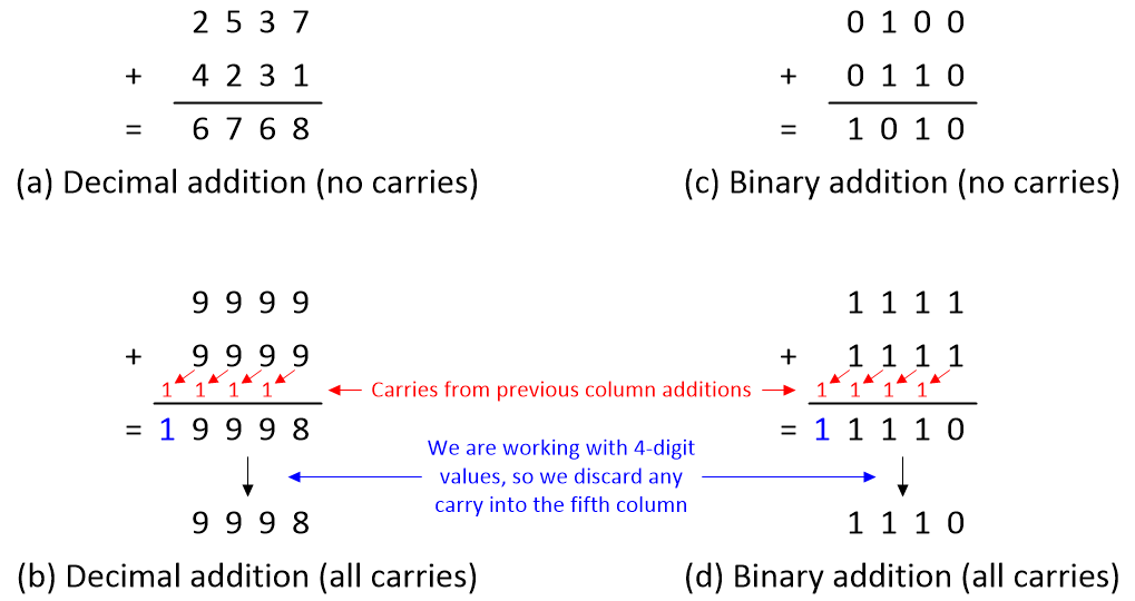
Examples of carries in decimal and binary addition (Source: Max Maxfield)
In the case of the examples with carries, since we have stated that we are working with 4-digit values, we are assuming that we have no way to store any additional digits, so we simply discard any carry-outs into the fifth column.
It’s perhaps worth pausing for a moment to contrast and compare the 9998 and 1110 results from (b) and (d) because this gives a hint as to what’s going on “under the hood,” as it were.
Now, this is where things start to get interesting. Suppose we are working with unsigned binary numbers and we decide to add 0011 + 1001 (or 3 + 9 in decimal). The result is 1100 (or 12 in decimal) as shown as (a) in the image below.
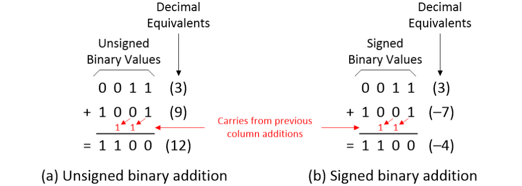
Adding unsigned and signed binary numbers by hand (Source: Max Maxfield)
Alternatively, suppose we are working with signed binary numbers, and we decide to add 0011 + 1001 (or 3 + (–7) in decimal). In this case, the result is 1100 (or –4 in decimal) as shown in (b) in the image above.
Wait! What? The values are identical for both cases! This is where we begin to appreciate the cunning of the signed binary format. It doesn’t matter whether we consider the values to be signed or unsigned because we add positive and negative values in exactly the same way. As we will soon see, this greatly simplifies the task of performing addition using logic gates.
The only “rule” is that whichever format we consider our values to be in (unsigned or signed), in order for the result to be valid, it must be able to fit into whatever size field we are using. In the case of our 4-bit values, this means the result must be in the range 0 to 15 if we are considering the values as being unsigned, or it must be in the range –8 to +7 if we are considering the values as being signed.
Adding Binary Numbers with Logic Gates
Since we are covering so many topics in this column, it’s probably worth noting that the number to which another number is to be added is called the augend from the Latin augendum, meaning “a thing to be increased.” By comparison, a number that is added to another number is called the addend from the Latin addere, meaning “to add.” And the result from adding two or more numbers together is called the sum from the Latin summa, from the feminine of summus, meaning “highest.”
We start by defining a 1-bit full binary adder. The symbol and truth table are shown below, where A is our 1-bit augend, B is our 1-bit addend, Cin (“carry in”) is the 1-bit carry coming from the previous stage, S is the 1-bit sum, and Cout (“carry out”) is the 1-bit carry going to the next stage (you’ll see what I mean by “previous stage” and “next stage” in a moment). There’s also such a thing as a 1-bit binary half adder, which has only the A and B inputs (no Cin), but we won’t be using that little rascal here.
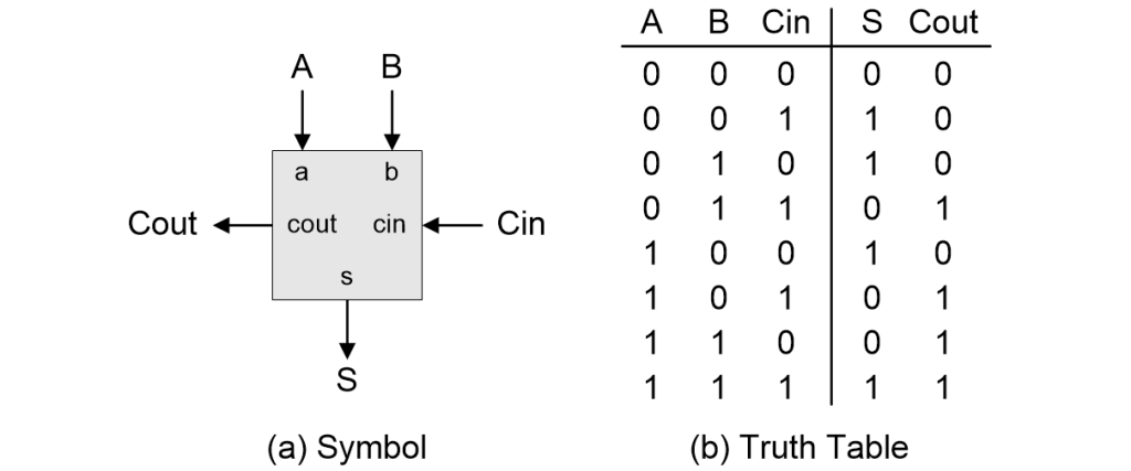
Defining a 1-bit full binary adder (Source: Max Maxfield)
As an aside, with respect to the truth table, some people prefer to have Cin in the left-hand input column with A and B in the two right-hand input columns. No problemo. Although this may make you pause for a moment’s thought, all you actually have to do is swap the A, B, and Cin labels at the top of the columns and leave everything else “as-is.”
It’s easy to come up with a collection of logic gates that will realize this truth table. As illustrated below, one common implementation involves a single 2-input OR gate, two 2-input AND gates, and two XOR gates (which are always 2-input). (If you are interested in delving deeper into this topic, just perform a Google search for “1-bit full adder.”)
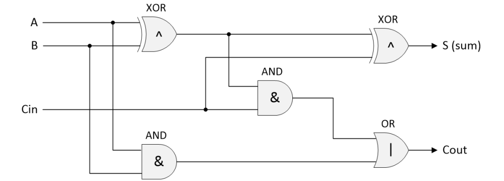
One possible gate-level implementation of a 1-bit full binary adder
(Source: Max Maxfield)
To match the calculations we’ve been performing by hand, our next step is to connect four instantiations of our 1-bit adder to create a 4-bit version as illustrated below.
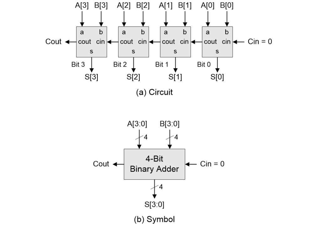
Building a 4-bit binary adder (Source: Max Maxfield)
In the case of the symbol, the angled lines with the number 4 associated with them indicate that these are 4-bit (four-wire) busses.
Observe that we force the Cin input feeding the least-significant bit (LSB) to 0 because there is no earlier stage driving this bit (we could use a half-adder for this stage, but we will need the Cin input later). The Cout from the LSB drives the Cin to the next bit, and so on down the line. For the purposes of our discussions here, we can assume that we discard (pay no attention to) the Cout from the most-significant bit (MSB). In the real world, we would use this “Carry” signal (along with another signal called “Overflow”) to tell us if the magnitude of the result from our addition exceeded our ability to represent it in the bits at our disposal, but that’s a story for another day.
For obvious reasons, this implementation is called a ripple carry adder because the carries ripple down the line. This is the slowest sort of adder, but it requires the least number of logic gates and it’s the simplest to understand, which makes it perfect for what we are talking about here.
Subtracting Binary Numbers with Logic Gates (Don’t Do It This Way!)
The number from which another number is to be subtracted is called the minuend from the Latin minuendum, meaning “thing to be diminished.” By comparison, a number that is to be subtracted from another number is called the subtrahend from the Latin subtrahendum, meaning “to subtract.” The result obtained by subtracting one number from another is called the remainder or the difference.
Based on everything we’ve discussed thus far, if you were to inadvertently fall through a timeslip and find yourself in the early 1940s, you already have the knowledge required to implement binary subtraction using primitive logic gates.
It’s important to understand that what I’m about to tell you is NOT the way we perform binary subtraction in the real world. However, it’s worth taking a little diversion to look at the way we might be tempted to do things if we didn’t know what I’m about to show you a little later in this column.
Our first step would be to define a 1-bit full binary subtractor. The symbol and truth table are shown below, where A is our 1-bit minuend, B is our 1-bit subtrahend, Bin (“borrow in”) is the 1-bit borrow coming from the previous stage, D is the 1-bit difference, and Bout (“borrow out”) is the 1-bit borrow going to the next stage.
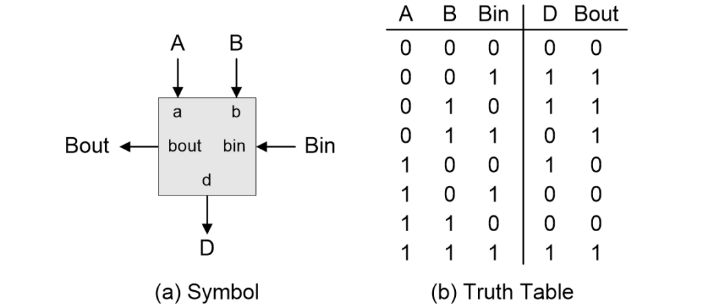
Defining a 1-bit full binary subtractor (Source: Max Maxfield)
You know the drill by now. If we were actually going to pursue this approach (which we aren’t), we would come up with a collection of logic gates that would realize this truth table, and then we would use four instantiations of our 1-bit subtractor to create a 4-bit version. You’ll just have to trust me that—like our 4-bit adder—this subtractor will happily work with both unsigned and signed binary values.
We don’t want to spend too much time on this, so let’s skip ahead to consider how we would implement both our 4-bit adder and 4-bit subtractor together, perhaps as part of a central processing unit (CPU).
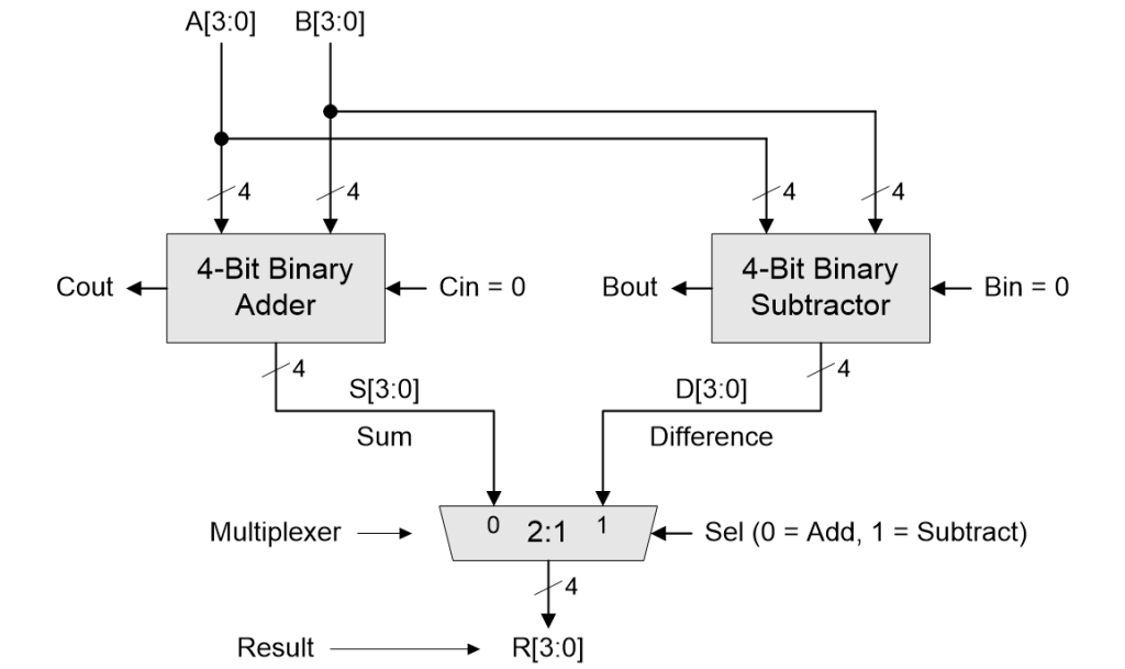
Implementing 4-bit binary addition and subtraction (Source: Max Maxfield)
The idea here is that we feed our 4-bit A[3:0] and B[3:0] signals into both the adder and subtractor, and we use a 4-bit 2:1 multiplexer to select the outputs of the operation in which we are currently interested and use these as our 4-bit result R[3:0].
Once again, for the purposes of these discussions, we will assume that we discard the Cout signal from the MSB of the adder and the Bout signal from the MSB of the subtractor.
Suppose we say our adder consumes A logic gates (for the purpose of these discussions we aren’t concerned with the actual number). Also suppose that our subtractor consumes the same number of gates as the adder. We might also say that our multiplexer consumes M logic gates. This means our total gate count for this realization is 2A + M. Furthermore, if we are intentionally vague, we could say that this implementation involves two stages of delay from its primary inputs to its primary outputs. Let’s make note of these facts for future discussions.
The problem with this solution is that we now have two relatively complicated functions—our adder and subtractor—consuming resources (logic gates and real-estate on our silicon chip) and constantly burning power, even though we’re only using one of these functions at any particular time. If only there were a better way…
Radix and Diminished Radix Complements
Before we proceed further, this is a good time to note that there are two forms of complement associated with every number system—the radix complement and the diminished radix complement—where the term radix refers to the base of the number system.
Under the decimal (base-10) system, the radix complement is also known as the ten’s complement and the diminished radix complement is known as the nine’s complement. In the case of the binary (base-2) system, the radix complement is also known as the two’s complement and the diminished radix complement is known as the one’s complement.
There’s a lot of confusion in this area. For example, should one write tens, ten’s, or tens’ complement? The problem is that you can run across all of these variants. Many style manuals recommend leaving out the apostrophe completely. However, many practitioners prefer to write these with an apostrophe in the form ten’s complement, nine’s complement, two’s complement, and one’s complement, and it is this approach we will use going forward in this paper.
If we use RC and DRC to represent the radix complement and diminished radix complement, respectively, then RC = DRC + 1 (contrariwise, DRC = RC – 1). You will come to appreciate this facet of things in a moment.
As an aside, before we proceed, did you ever wonder as to the origin of the ‘=’ character? Prior to the invention of this character, equality was usually indicated by a word such as aequales or aequantur, from the Latin aequlis, meaning “even” or “level” (for example, a mathematician write “6 + 2 aequales 8”). The first use of the modern equal symbol appeared in a 1557 AD book called The Whetstone of Witte, which was authored by the English mathematician Robert Recorde (1510-1558). In this tome, Recorde noted: “I will sette as I doe often in woorke use, a paire of parralles, or Gemowe lines of one lengthe, thus ‘=’ bicause noe 2, thynges, can be moare equalle.”
Subtracting Binary Numbers by Hand
When we are subtracting one number from another, it can be tricky to wrap our brains around the concept of borrowing. This is true even when we are working in decimal, not least because there are different ways of performing borrow operations (see my blog Neither a Borrower nor a Lender Be).
It may be that learning how to perform borrow operations in binary is equally mindboggling. I cannot say because I’ve never been obliged to do this. Instead, I perform these operations using one’s and two’s complements.
Suppose we wish to perform the calculation 5 – 2 = 3 in decimal. Well, that was easy, wasn’t it? How about in binary? Assuming we are still working with 4-bit values, this would be 0101 – 0010 = 0011. Like most things, this looks easy if you talk quickly and gesticulate furiously, but how did I do this? To be honest, I simply looked at the original calculation in decimal and then—since I know them by heart—I substituted the decimal values for their binary equivalents, thereby glossing over how we would actually perform the calculation. Speaking of which, consider the following illustration.

Who knows how to perform a borrow in binary? (Source: Max Maxfield)
We start with the LSB, which involves the operation 1 – 0 = 1. The next bit requires us to perform the operation 0 – 1, which will involve a borrow. I’m sure this is easy to learn and do but—as I just said—I’ve never actually been obliged to do so because there are other ways to achieve the desired result.
Let’s return to our original 5 – 2 = 3 calculation in decimal. Another way to view this is 5 + (–2) = 3. You may feel that this hasn’t substantially improved our position but let me explain further. We know that +2 in binary is 0010. What we want to do is to create the equivalent of –2 in binary, which, if we look at our signed binary table, we know to be 1110. The way we obtain –2 in binary is to generate the two’s complement of +2 in binary. There are three ways in which we can do this.
The first approach, which we might call “subtract and add,” is illustrated in (a) below. This involves us subtracting 0010 (+2) from 1111 (all ones) to generate the one’s complement 1101 (–3). Observe that we never have to perform a borrow while doing this. Next, we add 0001 (+1) to generate the two’s complement 1110 (–2).
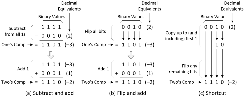
Generating one’s and two’s complements (Source: Max Maxfield)
The second approach is something we might call “flip and add” as illustrated in (b) above. In this case, starting with 0010 (+2), we simply flip (invert) all of the bits, 0s to 1s and 1s to 0s, to generate the one’s complement 1101 (–3). As before, we next add 0001 (+1) to generate the two’s complement 1110 (–2).
The third approach is a useful shortcut as illustrated in (c) above. Once again, we kick off with our 0010 (+2) value. Commencing with the LSB, we copy up to (and including) the first 1, and then we flip (invert) the remaining bits, leaving us with our two’s complement 1110 (–2).
This also works in reverse. If we start with 1110 (–2) and generate its two’s complement, we’ll end up with 0010 (+2). The point is that we can achieve all of this without ever having to perform a borrow operation. Furthermore, if we stick to using the (b) and (c) techniques, we don’t even have to perform a subtraction. If you haven’t already realized this, we are talking about a genuine “Tra-la” moment here because this opens the door to all sorts of possibilities.
For example, let’s return to our original problem of 5 – 2 (binary 0101 – 0010), which we can now rephrase as 5 + (–2) (binary 0101 + 1110) as illustrated below.
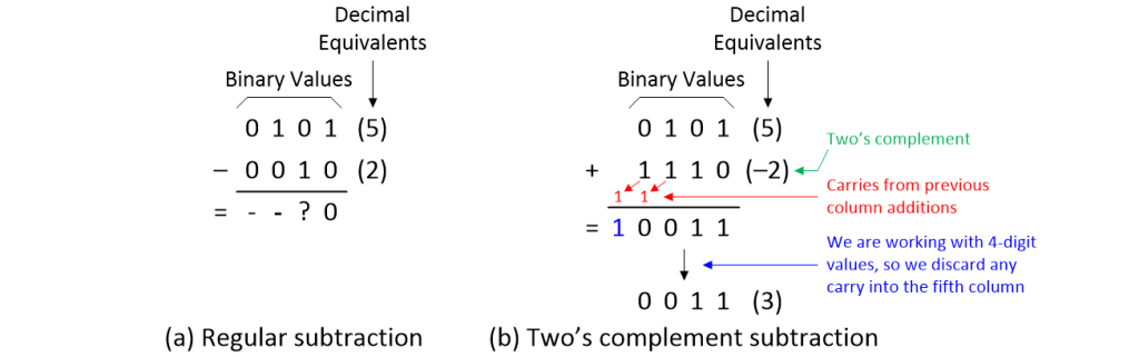
Subtracting with two’s complements (Source: Max Maxfield)
Performing this final step needs only addition. Remembering that we are dealing with 4-bit values, we discard any carry into the fifth column, leaving us with the expected result of 0011 (+3).
I know that all of this can seem to be “a bit much” (no pun intended) if you are a beginner. After just a little practice, however, you won’t even pause for thought while generating two’s complements and using them as part of your calculations.
Building One’s and Two’s Complementors with Logic Gates
In the previous section, we discussed how to perform binary subtraction by hand using the concepts of one’s and two’s complements. The next step is to implement these functions using logic gates. Since we are limiting ourselves to working with 4-bit values for simplicity, we start by creating a 4-bit one’s complementor. This is easy peasy lemon squeezy because it requires only four NOT (inverter) gates as illustrated in (a) below.
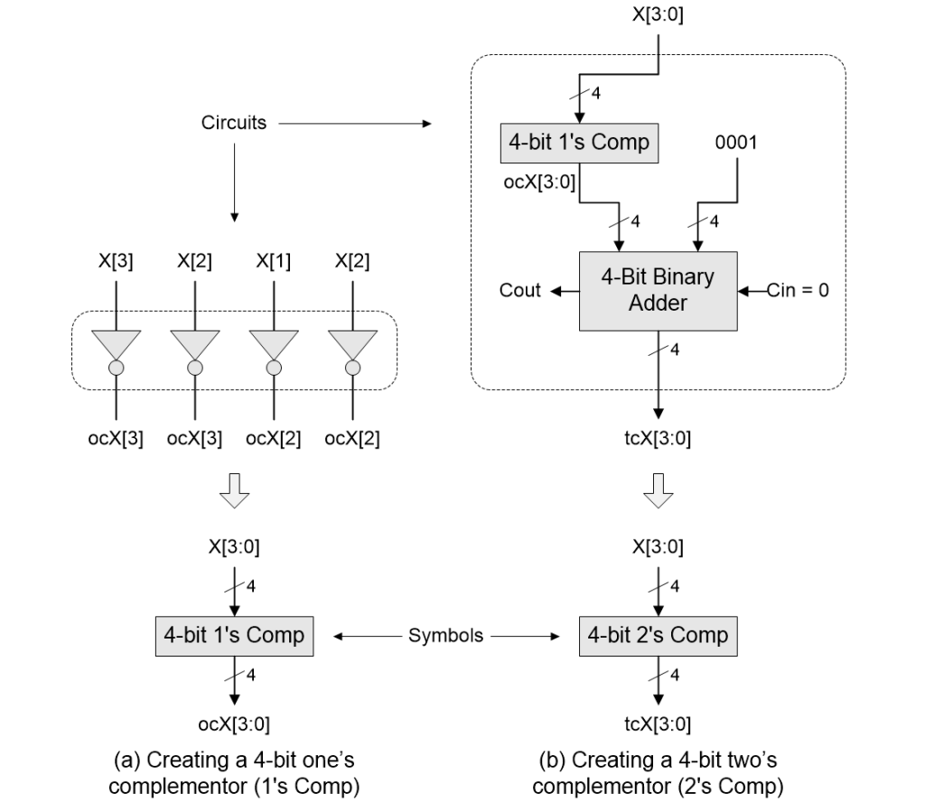
Building one’s and two’s complementors in logic gates (Source: Max Maxfield)
From our previous discussions, we know that the two’s complement of a binary number is its one’s complement plus 1, and we can achieve this using a 4-bit binary adder as illustrated in (b) above (observe that we connect this adder’s Cin input to 0 and we don’t use its Cout output at all).
Subtracting Binary Numbers with a Two’s Complementor (Don’t Do It This Way!)
Once again, based on everything we’ve discussed thus far, you might be tempted to imagine that a good solution to being able to add and subtract two 4-bit binary numbers would be an implementation looking something like the following:
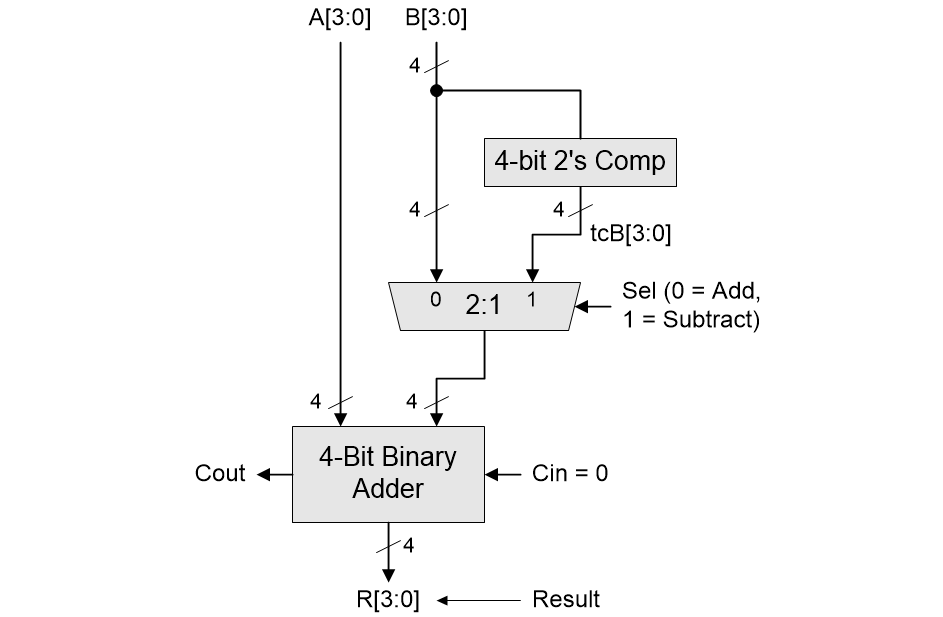
Using a two’s complementor to implement 4-bit binary addition and subtraction (Source: Max Maxfield)
As we see, inputs A[3:0] are always fed into our original 4-bit adder. The other inputs to our original adder are fed from a 4-bit 2:1 multiplexer, which is used to select between the B[3:0] inputs if we wish to perform addition (Sel = 0) or the two’s complements of the B[3:0] inputs (which we’ve called tcB[3:0]) if we wish to perform a subtraction (Sel = 1).
Cast your mind back to when we were considering using a 4-bit adder and a 4-bit subtractor. As you may recall, we assumed that our adder requires A gates, our subtractor requires the same, and our 4-bit 2:1 multiplexer requires M gates, giving a total of 2A + M. We also noted that that solution involved two stages of delay from its primary inputs to its primary outputs.
Now consider our latest solution. Remember that our two’s complementor is formed from a one’s complementor (four NOT gates) and a 4-bit binary adder. This means that our new solution consumes 2A + M + 4*NOT gates, which means it contains more gates than the original (sad face).
Even worse, and even if we exclude the one’s complementor on the basis that NOT gates are really fast, the worst-case path for our new implementation (the one passing through the two’s complementor) now involves three stages of delay from its primary inputs to its primary outputs (even sadder face).
So why are we waffling on about all this? Well, take a deep breath and prepare yourself for another “Tra-la” moment, because all is about to be revealed…
Subtracting Binary Numbers with a One’s Complementor (This IS the Way to Do It!)
Until now, we’ve connected the Cin input to our original 4-bit adder to 0. Let’s think about this. What would be the effect if we were to connect this to 1? In fact, this would be like adding 1 to the final result.
Hmmm. How do we generate a two’s complement of a binary value? By golly, you’re right! We add 1 to the one’s complement of that value. What this means is that we can replace our two’s complementor with a one’s complementor and use a 1-bit 2:1 multiplexer to feed the Cin input to our 4-bit adder as illustrated below.
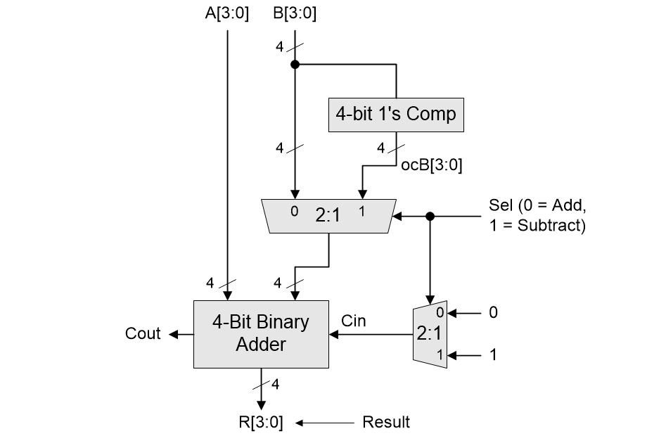
Using a one’s complementor to implement 4-bit binary addition and subtraction (Source: Max Maxfield)
The same Sel signal can be used to control both multiplexers. If we wish to perform an addition (Sel = 0), we select the B[3:0] inputs and we present 0 to the adder’s Cin input. Contrariwise, if we wish to perform a subtraction (Sel = 1), we select the one’s complements of the B[3:0] inputs (which we’ve called ocB[3:0]) and we present 1 to the adder’s Cin input.
If we exclude the gates used to form the one’s complementor and the 1-bit 2:1 multiplexer, our new solution can perform both addition and subtraction while consuming only A + M logic gates and involving only two stages of delay from its primary inputs to its primary outputs (happiest of happy faces)
All together now: “Tra-laaaaa!”
Unsigned, Sign-Magnitude, and Signed BCD Numbers
I know that we’ve wandered around a bit in our discussions, but hopefully you haven’t forgotten that the main topic of this paper is binary coded decimal (BCD). The thing is that everything we’ve looked at thus far is going to make it much easier to wrap our brains around the horrors delights that are to come.
Early in this paper, we introduced the BCD 8421 code in which each decimal digit is encoded using four binary bits. Let’s assume this is the code we are working with unless I tell you otherwise. Furthermore, for the purposes of these discussions, let’s assume that we are working with 4-digit BCD values.
If we decide to use these digits to represent only positive (unsigned) values, then we can represent the decimal values 0000 to 9999. This is shown as (a) in the diagram below.
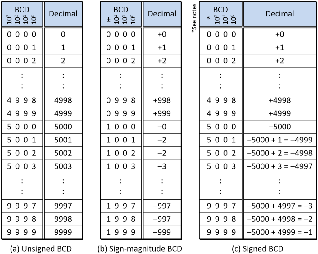
Comparison, of unsigned, sign-magnitude, and signed 4-digit BCD numbers (Source: Max Maxfield)
As you no doubt recall, in the case of our 4-bit binary values, our column weights from the most-significant bit (MSB) to the least-significant bit (LSB) were 23, 22, 21, and 20, which equate to 8, 4, 2, and 1, respectively. By comparison, in the case of our 4-digit unsigned BCD values, our column weights from most-significant digit (MSD) to least-significant digit (LSD) are 103, 102, 101, and 100, which equate to 1000, 100, 10, and 1, respectively.
If we wish to use BCD to represent both positive and negative numbers, then there are two commonly used approaches. The first is called sign-magnitude BCD. This is shown as (b) in the diagram above. In this case, the MSD acts as the sign bit and is used to indicate positive and negative values. In this diagram I’ve used 0 (binary 0000) and 1 (binary 0001) to indicate positive and negative values, respectively. In practice, it’s more common to employ two of the unused binary codes, typically 1100 and 1101, which are used to indicate positive and negative values, respectively. The remaining digits, which have the same column weights as before, are used to represent the magnitude of the number. Using this scheme, we can represent values from –999 to +999. As for sign-magnitude binary, we end up with two flavors of zero (+0 and –0), which can make our lives “interesting.”
An alternative method of representing positive and negative values is to use a signed BCD format. This is shown as (c) in the diagram above. In this case, the MSD may represent either a positive or negative quantity based on the combination of the digit itself and the column’s weight. With respect to a 4-bit signed BCD number, 0, 1, 2, 3, 4 values in the MSD represent 0, +1000, +2000, +3000, and +4000, respectively. However, a 5 in the MSD represents –5000, a 6 represents –5000 + 1000 = –4000, a 7 represents –5000 + 2000 = –3000, an 8 represents –5000 + 3000 = –2000, and a 9 represents –5000 + 4000 = –1000. All of the remaining digits continue to represent positive values. As a result, we can now use our 4-digit field to represent values from –5000 to +4999.
Adding BCD Numbers by Hand
This is where things get so cool that I’m squirming in my seat in excitement, because we can perform addition on unsigned and signed BCD values in much the same way we did with unsigned and signed binary numbers.
Consider adding the unsigned BCD values 2354 + 6430 = 8784, which equates to (+2354) + (+6430) = (+8784) in decimal. This is shown as (a) in the illustration below.
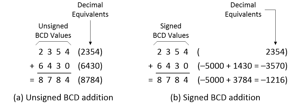
Now consider adding the signed BCD values 2354 + 6430 = 8784, which equates to (+2354) + (–3570) = (–1216) in decimal. This is shown as (b) in the illustration above. What this means is that it doesn’t matter whether we consider our BCD values to be unsigned or signed, we still perform the addition in exactly the same way.
Subtracting BCD Numbers by Hand
Subtracting BCD numbers by hand is easy, even if it involves performing borrow operations, because we treat these values in the same way as if we were working with regular decimal numbers, irrespective of whether we are considering them to be unsigned or signed BCD values. Consider a simple example involving 4354 – 2430 = 1924, which equates to (+4354) – (+2430) = (+1924) in decimal, as illustrated below.

At some stage we will need to decide how we are going to perform subtraction operations using logic gates. We could replicate all of our earlier binary-centric discussions but—instead—let’s simply acknowledge that we are going to employ nine’s and ten’s complement techniques.
Let’s return to our original 4354 – 2430 = 1924 calculation. Once again, another way to view this is as 4354 + (–2430) = 1924. So, what we want to do is to create the equivalent of –2430 in BCD (i.e., the ten’s complement of +2430). Based on our previous discussions, we know this will be 7570 in BCD, which equates to –5000 + 2570 = –2430 in decimal.
There are three ways in which we can do this. First, we have the “subtract and add” approach as illustrated in (a) below. This involves us subtracting 2430 (+2430) from 9999 (all nines) to generate the nine’s complement 7569 (–2431). Next, we add 0001 (+1) to generate the ten’s complement 7570 (–2430).
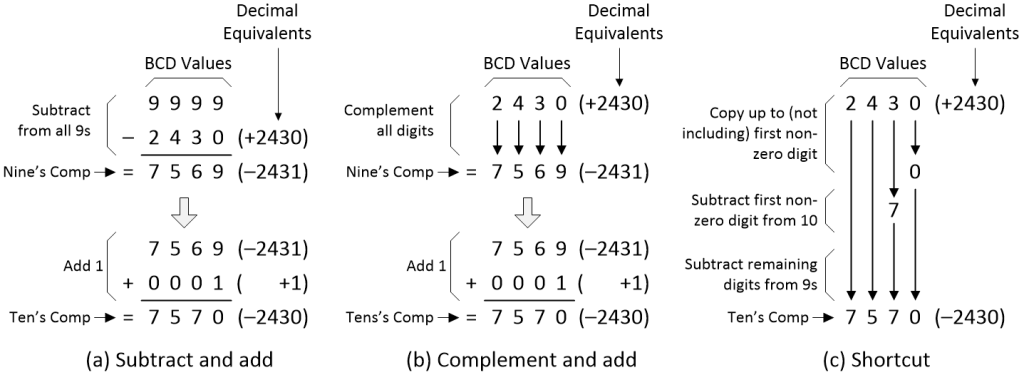
Generating nine’s and ten’s complements (Source: Max Maxfield)
Alternatively, we have the “complement and add” technique illustrated in (b) above. In this case, we simply remember that the complement of 0 is 9, the complement of 1 is 8, the complement of 2 is 7, etc., and then we jot the complements down to generate the nine’s complement 7569 (–2431). As before, we then add 0001 (+1) to generate the ten’s complement 7570 (–2430).
The third approach is a useful shortcut as illustrated in (c) above. Once again, we kick off with our 2430 (+2430) value. Commencing with the LSD, we copy up to (but excluding) the first non-zero digit. We then subtract the first non-zero digit from 10, after which we complement any remaining digits by subtracting them from 9, leaving us with our ten’s complement 7570 (–2430).
As before, this also works in reverse. If we start with 7570 (–2430) and generate its ten’s complement, we’ll end up with 2430 (+2430). And, as before, the point is that we can achieve all of this without ever having to perform a borrow operation.
OK, let’s see this in action by returning to our original problem of 4354 – 2430 = 1924 as illustrated in (a) below. If we rephrase this as 4354 + (–2430) = 1924, then—using ten’s complements—our BCD calculation can be performed as 4354 + 7570 = 1924, which equates to (+4354) + (–2430) = (+1924) in decimal, as illustrated in (b) below.
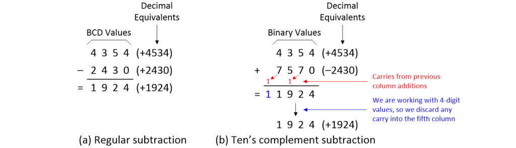
Subtracting with ten’s complements (Source: Max Maxfield)
Once again, remembering that we are dealing with 4-digit values, we discard any carry into the fifth column, leaving us with the expected result of 1924 (+1924).
Creating a 1-Digit BCD 8421 Adder
When it comes to adding and subtracting BCD numbers using logic gates, our first step will be to create a 1-digit full BCD 8421 adder (remember that each BCD digit is represented using four binary bits).
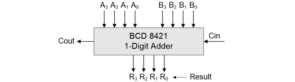
Symbol for a 1-digit full BCD 8421 adder (Source: Max Maxfield)
A common way to determine which logic gates we are going to use is to create a truth table for the function and then perform Boolean and/or Karnaugh map minimizations, so why didn’t I include a truth table in the above diagram?
Well, remember that if we wish to add two BCD digits together, there are 100 different possibilities, 0 + 0 = 0, 0 + 1 = 1, 0 + 2 = 2… 1 + 0 = 1, 1 + 1 = 2, 1 + 2 = 3… 2 + 0 = 2, 2 + 1 = 3, 2 + 2 = 4 etc., which equates to 100 lines in our truth table. We’ve also got to take the Cin input into account. Since Cin may be 0 or 1, this means our truth table would now contain 200 lines. You can create this table and use it to generate a gate-level implementation if you wish, but I think I’ll pass.
Another possibility would be to use some form of read-only memory (ROM) as a look-up table (LUT). We could use the inputs to our adder as the address pointing to 5-bit words in the LUT. Since we have nine input bits to our adder (A3..A0, B3..B0, and Cin), this means we would need a ROM with 29 = 512 words. Of course, remembering that a BCD digit uses only 10 out of the 16 possible 4-bit binary combinations, we would have a lot of wasted rows associated with the unused combinations. Also, since the width of memories is usually measured in multiples of 8-bit bytes, and we have only 5 output bits, we would be wasting 3 bits in each byte.
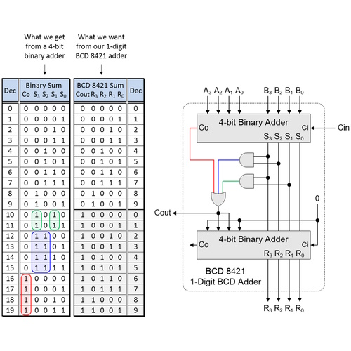
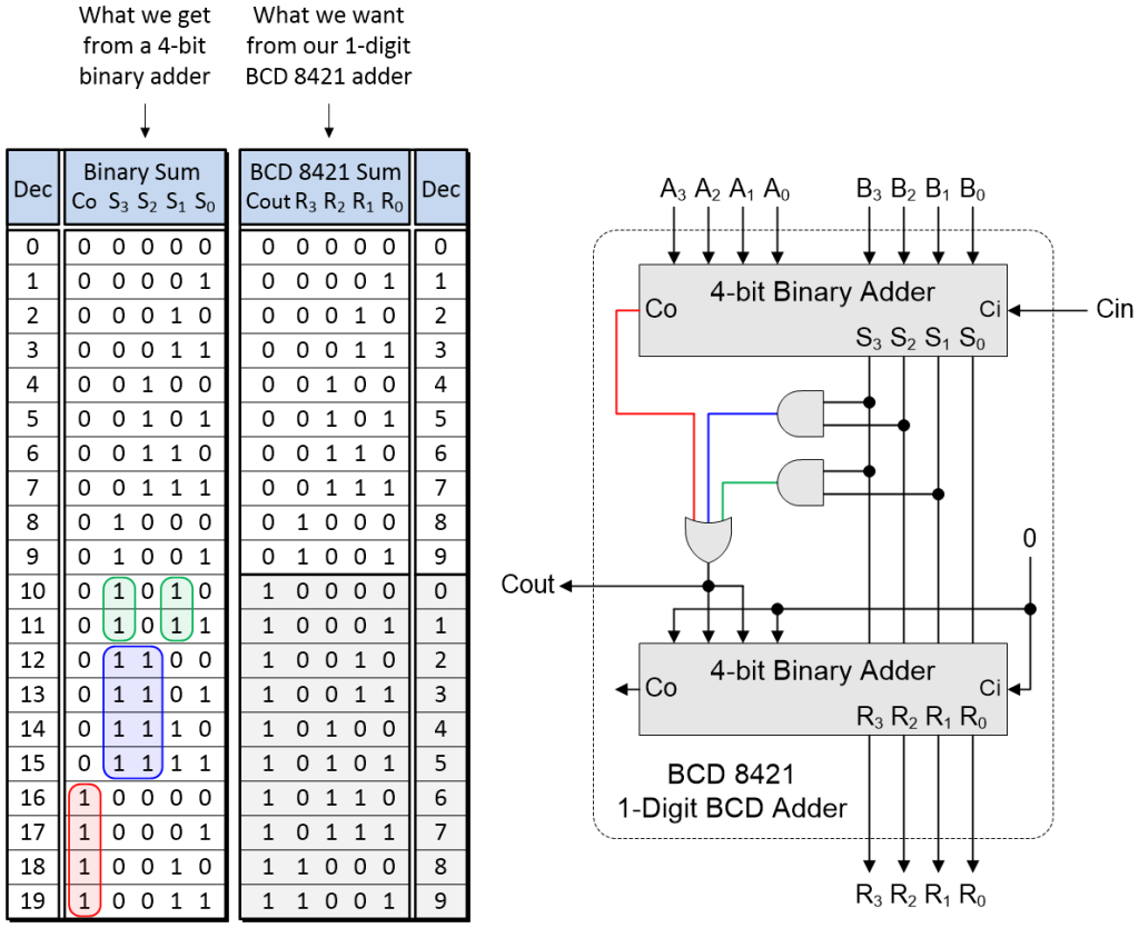
Can we come up with a better way? Well, as fate would have it, a rather interesting implementation is possible using two 4-bit binary adders as illustrated below.
Implementing a 1-digit BCD 8421 adder using two 4-bit binary adders
(Source: Max Maxfield)
The truth table on the left shows the outputs we can obtain from the first 4-bit binary adder based on all possible (legal) combinations of our A3..A0, B3..B0, and Cin inputs. The truth table on the right shows the corresponding results we wish to obtain from our 1-digit BCD 8421 adder.
Let’s start with the Cout (“carry out”) signal in the right-hand truth table. We want this to be 0 for the first 10 rows and 1 for the second 10 rows. We can achieve this as an OR of the rows associated with the input combinations highlighted red, blue, and green in the left-hand truth table. The rows corresponding to the red area can be identified using a copy of the Co (“carry out) signal from the first 4-bit binary adder. The rows corresponding to the blue area can be identified using an AND of outputs S3 and S2 from the first 4-bit binary adder. Similarly, the rows corresponding to the green areas can be identified using an AND of outputs S3 and S1 from the first 4-bit binary adder.
Now let’s turn our attention to the second binary adder, whose right-hand set of inputs are fed by the S3..S0 outputs from the first 4-bit binary adder. As we see in the right-hand truth table, for the first 10 rows, which correspond to Cout = 0, the R3..R0 outputs from the second 4-bit binary adder are identical to the S3..S0 outputs from the first 4-bit binary adder. We can achieve this by forcing the left-hand set of inputs to the second binary adder to be 0000.
Now consider the last 10 rows in the right-hand truth table, which correspond to Cout = 1. In this case, the R3..R0 outputs from the second 4-bit binary adder are equal to the S3..S0 outputs from the first 4-bit binary adder plus 0110 (or 6 in decimal). We can achieve this by forcing the left-hand set of inputs to the second binary adder to be 0110.
The clever part here is that we use the Cout signal itself to determine whether the left-hand inputs to the second binary adder are 0000 or 0110.
Adding and Subtracting BCD Numbers with Logic Gates
In the same way that we used a 4-bit one’s complementor to implement a 4-bit binary addition and subtraction solution, we can use a 4-digit BCD 8421 nine’s complementor to implement a 4-digit BCD 8421 addition and subtraction solution as illustrated below.
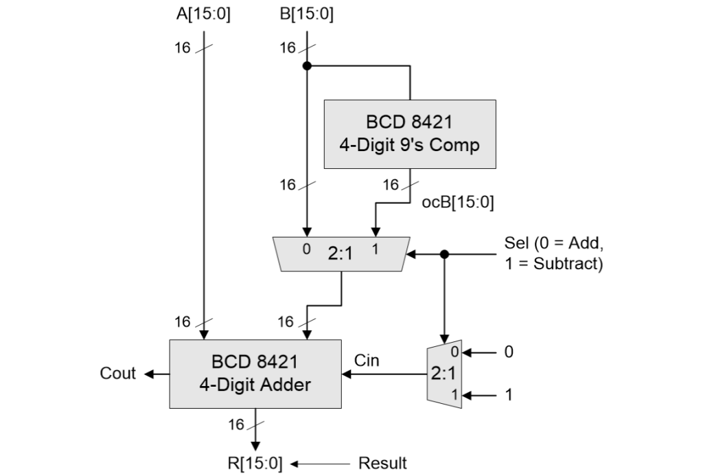
Using a nine’s complementor to implement 4-digit BCD addition and subtraction (Source: Max Maxfield)
On the one hand, this is really rather tasty. On the other hand, there’s an elephant in the room and a fly in the soup (I never metaphor I didn’t like). In the case of our one’s complementor, all we had to do was flip (invert) each binary bit using a NOT gate. Sad to relate, the same is not true of our BCD 8421 nine’s complementor for reasons that are obvious when we look at the tables below.
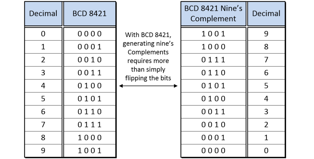
Bit patterns for BCD 8421 digits and their nine’s complements
(Source: Max Maxfield)
We could, of course, create a truth table with the four BCD 8421 bits as inputs and the corresponding four BCD 8421 nine’s complement bits as outputs, and then use this to determine the logic gates required to translate from one form to the other, but using only NOT gates is preferable for reasons of speed, power, and reducing our gate count. If only we had access to something like a self-complementing BCD code…
Self-Complementing (and Other) BCD Codes
And so we return to the wisdom of the ancients. As we previously discussed, BCD 8421 is said to be a weighted code because each of its columns has a “weight” associated with it. Many other weighting possibilities are possible, including BCD 4221, BCD 4311, BCD 5421, BCD 7421, and… the list goes on. Some of these encodings are self-complementing, such as BCD 2421 (a.k.a. Aiken) and Excess-3 as illustrated in the table below.
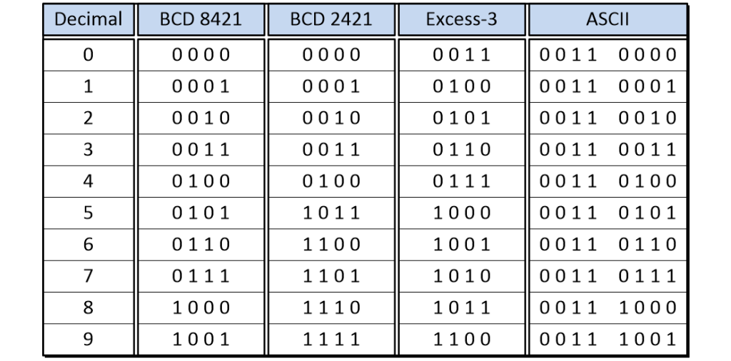
Self-complementing (and other) BCD codes (Source: Max Maxfield)
Note that Excess-3, which is obtained by adding 0011 (3) to each of the BCD 8421 codes, is not classed as a weighted code because it isn’t possible to assign column weights that add up, if you see what I mean.
The only reason for including the American Standard Code for Information Interchange (ASCII) encodings for the decimal digits 0 through 9 in this table is to highlight the fact that this is also a form of BCD encoding. In fact, this is also referred to as a zoned decimal numeric representation in which each decimal digit is stored in one byte, with the lower four bits encoding the digit in BCD form, while the upper four bits, called the “zone” bits, are (usually) set to a fixed value.
The great thing about self-complementing BCD codes like Excess-3 is that we can generate their nine’s complements by simply inverting their bits using NOT gates. Of course, switching to something like Excess-3 does mean that we will have to replace our 1-digit BCD 8421 adder with its 1-digit BCD Excess-3 counterpart, but we’ll leave that as an exercise for the reader (that would be you).
Using BCD to Represent Fixed-Point and Floating-Point Numbers
A lot of people assume that BCD can be used only to represent unsigned and signed integers, but this is absolutely not the case. In reality, BCD can be used to represent any form of number we wish. As we see in the illustration below, for example, BCD can be used to represent both fixed-point and floating-point values.
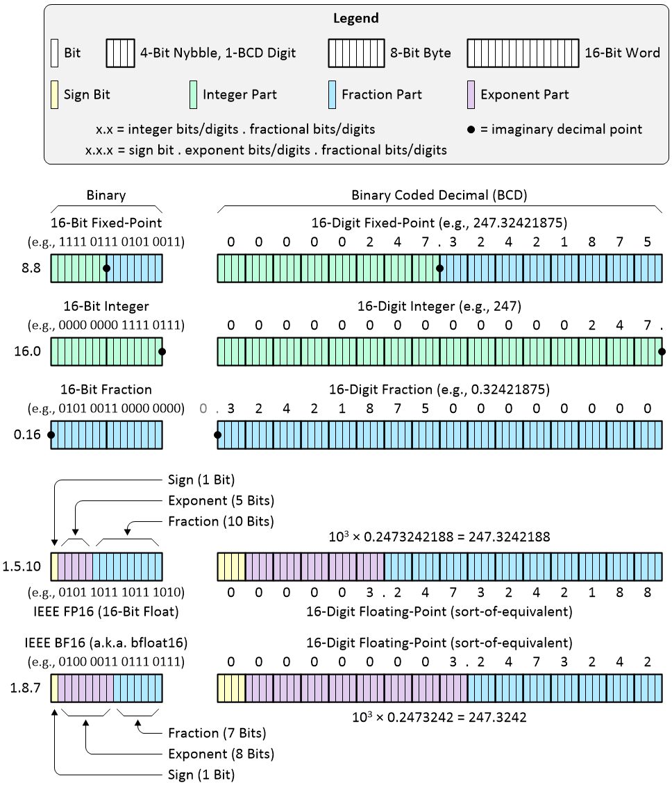
Using BCD to represent fixed-point and floating-point numbers
(Source: Max Maxfield)
In the case of fixed-point, we have the generic form that includes both an integer part and a fractional part. Also, we can have forms that represent only an integer part or a fractional part.
It’s important to note that, although I chose to use 16-bit binary and 16-digit BCD values in this illustration, we aren’t comparing apples to apples here (apples to aardvarks would be a closer analogy). For example, a 16-bit binary number can represent 216 = 65,536 different values. By comparison, a 16-digit BCD number can represent 1016 = 10,000,000,000,000,000 different values.
In the case of binary floating-point, I’ve chosen to present two common formats here. FP16, which is the half-precision floating-point format from the IEEE 754 standard, has a sign bit, five exponent bits, and ten fraction bits. By comparison BF16, where BF stands for “Brain Floating-Point,” which was originally developed by Google Brain (an artificial intelligence (AI) research group at Google), boasts a sign bit, eight exponent bits, and seven fraction bits.
BF16, which has a larger dynamic range but less precision than FP16, is increasingly finding use in AI applications for which it typically performs as well as the 32-bit IEEE FP32 single-precision floating-point format while delivering higher performance and lower memory usage because the additional mantissa bits in FP32 are simply dropped.
To be honest, I’m a bit fluffy around the edges with respect to floating-point formats in general, so please take the examples shown in the illustration above with a “grain of salt” because I basically threw them together to give us something to talk about.
BCD Usage in the Past and Present
When people first started building electromechanical and electronic digital computers in the early 1940s, they thought it made sense to implement them as decimal machines; that is, computers that represent numbers and addresses in decimal as well as providing instructions to operate on those numbers and addresses directly in decimal, without conversion to a pure binary representation.
Early computers that were exclusively decimal include the ENIAC, IBM NORC, IBM 650, IBM 1620, IBM 7070, and UNIVAC Solid State 80. In these machines, the basic unit of data was the decimal digit, encoded in one of several schemes, including BCD.
Interestingly enough, in the aftermath of World War II, it was discovered that a full-fledged mechanical computer called the Z1 had been built in Germany before the start of the war. Created by a German engineer called Konrad Zuse, the ZI was founded on performing its calculations using binary floating-point representations.
By the time microprocessors came along, binary representations had come to the fore, but several families offered limited decimal support in the form of BDC addition and subtraction and/or instructions to convert byte-wide BCD data (packed and unpacked) into binary format.
BCD’s main virtue, in comparison to binary systems, is its more accurate representation and rounding of decimal quantities, as well as its ease of conversion into conventional human-readable representations. For example, 0.1 (1/10) in decimal is easy to understand, while 0.1 in binary is 0.00011001100110011… (that is, the pattern of 0011 repeats infinitely). The bottom line is that it isn’t possible to store the binary equivalent of decimal 0.1, for example.
As a result—although BCD per se is not as widely used as in the past, and although it is limited or unavailable in newer instruction sets—decimal fixed-point and decimal floating-point formats are still important and continue to be used in many financial, commercial, and industrial computing applications in which the subtle conversion and fractional rounding errors that are inherent in binary formats cannot be tolerated.
For example, many countries mandate by law that financial calculations performed on a computer provide exactly the same results as if they were performed by hand using pencil and paper. In turn, this means that these calculations must be performed using some form of BCD. Although the majority of computers offer only limited hardware support for calculations to be performed in BCD, such calculations can be implemented using software techniques.
Also of interest is that fact that the majority of the world’s electronic pocket calculators—whose usage involves a lot of input and output coupled with comparatively little computation—perform their magic using only BCD representations (for some reason, the majority of users prefer a calculation like 0.1 + 0.2 to offer a result of 0.3 rather than 0.299999…).
As just one real-world example that is close to home, whilst writing this column, I took a break to chat with my friend Jonny Doin, who is the Founder and CEO at GridVortex Systems in Brazil. The folks at GridVortex offer deeply embedded engineering design and consulting services for safety-critical and mission-critical systems.
When I told Jonny what I was working on, he replied: “What a coincidence! I just passed the last 10 hours working on porting my single-clock-cycle binary-to-BCD logic to a full serial processing logic implementation. This is part of my FPGA embedded framework. The BCD algorithm plays a central role in a PRINT_BIN2ASC block, which takes a configurable width binary number and prints a fully formatted ASCII stream of chars into a stream FIFO in much the same way as a C printf(“%d”, var) statement.”
I asked Jonny to tell me more, and he offered to write it up in a form I could use. I was going to include Jonny’s offering here, but since this column has already grown beyond all recognition, I decided to post it as a standalone column—GridVortex Meets BCD—on my Cool Beans Blog.
Solution to Black Box Problem
Last, but certainly not least, there are several ways of attacking the problem posed at the beginning of this column. My favorite solution was generated by my chum George Harper. Shortly after I presented this puzzle to George, he responded by email saying: “I don’t think it can be done.” This was followed a little later by a message saying: “I stand corrected, I have the glimpse of an idea as to how it might be done.” The following morning, after a sleepless night, a triumphant email arrived saying: “It can be done, and this is how you do it!”
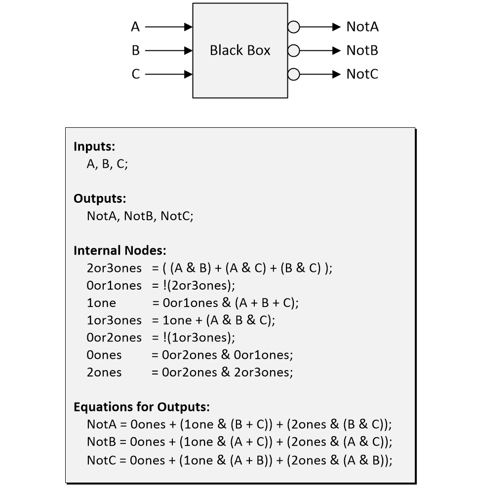
In this case, ‘&’ represents AND, ‘+’ represents OR, and ‘!’ represents NOT. In particular, observe that George’s solution employs only two NOT gates, which we see associated with the equations for the internal signals 0or1ones and 0or2ones.
Posing and solving problems like this used to be a popular pastime for the logic designers of yesteryear. How about you? Do you have any puzzles of this ilk that you’d care to share with the rest of us? Also, do you have any nuggets of knowledge, tidbits of trivia. or tall tales to tell with respect to anything related to BCD?


I’m looking forward to seeing suggestions for how to build a 1-digit BCD adder that works with one of the self-complementing BCD encoding schemes.
Max, that’s an excellent article, as always. And that is not because you so generously published my writeup on my FPGA framework :^)
I have to say I decided to unlearn binary and decimal adder logic, just to re-learn from your engaging construction of one’s complement + carry chain, and application to nine’s complement + bcd adder chain.
The pleasure of pure digital design.
Thanks Jonny — you are very kind — and, like you, I love pure digital design — did you ever read the book “Hacker’s Delight” by Henry Warren (https://www.amazon.com/dp/0321842685)? It’s jam-packed with tips and tricks for the coding side of things, much of which can subsequently be employed in the logic side of things.
Oh, I have used many times algorithms from Hacker’s Delight.
From tricks of division by constants to more arcane things like square root on a small 8bitter.
It is a book to keep in the bedside stack.
Hi, Johnny.
You wrote “The pleasure of pure digital design.” Amen.
And if I remember correctly , adding 1’s Complement with a “Hot 1” into low order position does a subtract and has been used in computers.
Here is an evolving “source syntax” that I think is easy to parse using C#; Please excuse the messiness.
Then it is pretty easy to evaluate the Boolean expressions for control and numeric expressions for values.
name : value // initialize value
name : value1@ value2 // value = value1 at t = value2
name : value1@ value2 : value3 // value = num1 at t = num2 repeats each num3 interval
name : name ? bool expression
net : net1 ? net2 // bool net node value equal to bool net1 if bool net2 is true else false
net : bool expression ? bexp2 // bool net node value equals exp1 if bool exp2 is true else false
name ? bool expression
name = numeric expression
bus = bus2 ? net // bus1 value equals bus2 value if net is true else zero
bus = expression ? net : 0 // bus equals expression value if net is true else zero
Here is an input snippet that I am n the process of parsing, compiling/building and running in debug mode.
// comment
clk:0 @ 0 : 2
clk:1 @ 1 : 2
prime : 1
//a[0..3]:b[0..3]?c.4
a? prime |k&!j
b? a&!k
c? b&!a
d? c&!b
e? d&!c
f? e&!d
g? f&!e
h? g&!f
j? h&!g
k? j&!h
!prime? a
//+a?prime
// ! means assign false ? if the expression is true
!a? !k&b
!b? !a&c
!c? !b&d
// A signal expression may also be used
!d? _tfd
!e? _tfe
!f? _tff
!g? _tfg
!h? _tfh
!j? _tfj
!k? _tfk
I must confess that I cheated, though. I went directly to George Harper answer for the 2 inverter blackbox problem.
Kudos, @George, nice rendering.
That’s cheating LOL
On a related note about Decimal early machines, there is an interesting British machine from 1951 that would be worth mentioning on Decimal Computers.
It is the WITCH computer, an automatic calculation machine built to perform long computations for the British Atomic programme.
It had relays for the control program sequencer, and Dekatron valves as decimal number storage and processing.
It took over 10 seconds to complete a calculation, but could churn for days on long lists of decimal calculations.
The remarkable thing is that WITCH is still operational, and is in fact the oldest computer ever built that is original and running today, in the national museum of computing in Bletchley Park.
I went there in person to see its reboot 10 years ago.
I’ve been to Bletchley Park, but I don’t recall seeing the WITCH — had I known about it I would have asked to see it — maybe next time 🙂
Oh, they had the Colossus on display, but I already knew about the WITCH restoration and upcoming reboot, and went to see it instead.
tnmoc a has quite impressive collection, including working computers with core memory and paper tape printers.
Hi Max, that was an excellent ‘reference column’. Back in the 1980s, Flowpro Control Software actually had a BCD register type because seven segment displays and BCD switches were so prevalent then. BCD conversion was automatic when data was moved to or from binary registers or I/O. We eventually removed it to make room for subtypes such as time format, integer and other. I still have some of those BCD thumbwheel switches. BTW, I can solve the puzzle without using any NOT Gates. I would just use three parallel Flowpro Machine flowcharts.
Hi Ron, you say “I can solve the puzzle without using any NOT Gates. I would just use three parallel Flowpro Machine flowcharts,” but then you would be using implicit inversions you little scamp.
I think you are referring to ‘implicit inversions’ as a software construct? In the case of inverting a signal (something that is hardly ever done in an event driven system like Flowpro) the solution is a test (decision) circuit construct, two action constructs and a storage construct. Not very efficient when compared to a NOT Gate but it does the job without using one. One beauty of Flowpro is that it plays well with Boolean circuits which will be more efficient in some constructs. For instance, developing a Boolean expression to be input to a decision (test) circuit. The real issue with Flowpro is parallel thinking.
Quite a blast from the past, thanks for this overview.
Around 1980 I implemented a serial binary to BCD conversion in TTL logic, for displaying and comparing the timestamps of the three (majority voting) Spacelab computers.
Based on that same principle, in 1999, I wrote a very fast 24 bit binary to 8 digits packed BCD conversion for the i8051 CPU, downloadable here:
https://ademu.home.xs4all.nl/download/codesnippets/8051/asm/bin24bcd.asm
I just took a look at your assembly program — thanks so much for sharing this 🙂
Hi Max It your Nemesis Crusty,
Great article.
I was thinking about your PE series and there is always the problem with low count I/O pin processors, have I got enough I/O pins to spare?
Your Arduino slide uses an 8 bit port for a one digit display, (I know you are explaining the subject in simple terms).
“we could use a CD4511 BCD-to-7-segment decoder”, this is 4 I/O pins minimum. helps to reduce I/O count.
I recently had to use a 7 segment led display and only had two I/O pins left on the processor.
Ended up driving the display with an LS74146 serial to 8 bit parallel shift register, outputs of which have more than enough to blow a led without limiting resistors.
Not BCD, but it does mean that you can drive any possible combination of a 7-seg display elements with 7bits serial over two wires and even have the decimal point using the 8 bit as the driver 8th segment dot.
Best Crusty
“It’s your nemesis, Crusty.” Hi Crusty — now I’m thinking of the opening lyrics to The Sounds of Silence by Simon and Garfunkel “Hello Crusty, my old friend, I’ve come to talk with you again…” As you say, in my articles in Practical Electronics, I’m currently using 8 of my Arduino’s digital output bits to drive a single 7-segment display (including its DP “Decimal Point”). In future installments we are going to look at lots of different ways of driving multiple 7-segment displays using fewer pins — in addition to shift registers (which, as you say, allow us to drive all of the segments individually), we will also be using multiple BCD-to-7-segment decoders, and a single BCD-to 7-segment decoder while multiplexing the displays, and… but you’ll have to wait LOL
Well done!
For your next act, how about some logic blocks? Such as the TTL in the TI yellow book.
Then microprogrammed controls would be fun.
This nonsense of using a description rather than logic for design entry has to end.
Some languages have recently added conditional assignment statements and also support Abstract Syntax Trees with an API. Believe me, there needs to be a rebirth of Logic Design.
There has always been a shortage of logic designers (who are now nearly extinct). No, the if() statement is not sufficient.
You and I claim to be logic designers, and I have a syntax and parser/builder/debugger in development.
“I have a syntax and parser/builder/debugger in development.” Email me (max@eejournal.com) when you have everything up and running — there could be an article there 🙂
If you have Windows, Visual Studio 2022, and want to peek at my Bloop project … Boolean Logic oop, I will put it on DropBox or Git.
This started out as a new kind of computer that took only a couple of hundred LUTs and 3 dual port Block Rams on an FPGA that had unbelievable performance. No body cared mainly because it was not supported by a tools provide ((I understand)
I have been frustrated because of the management decision that Verilog MUST be used for source entry because “Verilog can be simulated”. So here I am developing my own tool, trying to show “the right way”.
I had/have a CEngine on GIT and DropBox . I will try to post a link to download a demo. Soon I hope to have Bloop ready to go. Later…
Me to me: I cannot find the link, will have to try something different. Sorry
A = 11 + 12 * 13 – (14 + 15) * 10 = ???
Well, assuming normal mathematical precedence of operators (as opposed to left to right evaluation) I would say the answer is –123
12*13=156
156 + 11 = 167
14 + 15 = 29
29*10 = 290
167 – 290 = –123
You say: Original was A = B + C * D – (E + F) * A (converted to Hexadecimal values)
All I can see you doing with this is saying
A + A * (E + F) = B + (C * D)
So A * (1 + E + F) = B + (C * D)
You say: Given a typical cpu with a single alu(+,-,*,/), there is a functional piece missing. What is it?
So long as you have a parser that understands parentheses and normal mathematical precedence of operators and can push intermediate values on the stack, I don’t see a problem — please elucidate 🙂
I would love to see it — but I’m 100% loaded at the moment (and not in a good way with alcohol) — there’s just so many fun things to do and not enough time to do them all 🙁
Meanwhile, there are some interesting math expressions. I like this one which is a slight modification of one posed by Brian Bailey back in the days of All Programmable Planet:
Evaluate:
A = 11 + 12 * 13 – (14 + 15) * 10 = ??? ; Original was A = B + C * D – (E + F) * A (converted to Hexadecimal values)
Given a typical cpu with a single alu(+,-,*,/), there is a functional piece missing. What is it?
Then I won’t bother you.
Tra-laaaaa!!!! What a great high performance work-out with implementing fixed point arithmetic. Kudos Max and I now know why you are “Max the Magnificent”. Karnough Mapping (https://www.geeksforgeeks.org/introduction-of-k-map-karnaugh-map/) is one additional approach to add for the solution to the black-box problem.
Hi Dan — I love Karnaugh maps — I’m always blown away by what a great idea they are. Are you familiar with Reed-Müller logic? The idea here is that some digital functions can be difficult to optimize if they are represented in the conventional sum-of-products or product-of-sums forms, which are based on ANDs, ORs, NANDs, NORs, and NOTs. In certain cases it may be more appropriate to implement a function in a form known as Reed-Müller logic, which is based on XORs and XNORs. The reason I mention this here is that one indication as to whether a function is suitable for the Reed-Müller form of implementation is if that function’s Karnaugh Map displays a checkerboard pattern of 0s and 1s. I discuss this in exhilarating (some may say excruciating) detail in Appendix C of my book Bebop to the Boolean Boogie (https://www.amazon.com/dp/1856175073)
Dear Max,
It took four days for me to reach the similar solution of the NOT puzzle, if it were my student years (70s) I believe it would be much less. I am a bit disappointed with myself but we get old.
My solution has an extra stage, I have 8 unary outputs, i.e. assuming the input is a binary number, only one of the outputs from 0 to 7 is “1” at a time. The desired output is obtained by ORing the unary outputs. As a matter of fact you can get any arbitrary three output truth table by this method.
Thank you for your excellent column and I am expecting more puzzles, cheers!
Hakkı
inputs: A B C (A is MSB)
unary outputs: U0 U1 … U7
not outputs: notA notB notC
D = !(AB+AC+BC) // 0or1ones
E = !((ABC+D)(A+B+C)) // 0or2ones
U0 = DE
U1 = CD
U2 = BD
U3 = BCE
U4 = AD
U5 = ACE
U6 = ABE
U7 = ABC // not used
notA = U0+U1+U2+U3
notB = U0+U1+U4+U5
notC = U0+U2+U4+U6
Hi Hakki — I’m glad you enjoyed finding the solution — it’s a great feeling when you can finally say “Yes! I got it!” 🙂 Thanks so much for letting me know — Max
ChatGPT Mar 14 Version failed to produce a correct answer, in fact it is far from a solution, here is its first try:
To solve this problem, we can use a combination of AND and OR gates to implement the logical inversions of the inputs. Here’s one possible solution using two NOT gates, one OR gate, and three AND gates:
NotA = B OR C
NotB = A OR C
NotC = A OR B
Explanation:
To implement NotA, we can use an OR gate to combine inputs B and C. If either B or C is 1, the output of the OR gate will be 1, which will invert A to 0. If both B and C are 0, the output of the OR gate will be 0, which will invert A to 1.
………
Thank goodness it failed — I think that when something like ChatGPT can solve a problem like this on its own, then we’ve all got problems 🙂
Hi,
Gemini 2.5 got the correct answer, I think it cheated and found the solution somewhere (that is what I want believe in).
The answer starts with
NOT(M)=NOT((A AND B) OR (B AND C) OR (C AND A))
NOT(P)=NOT(((A OR B OR C) AND NOT(M)) OR (A AND B AND C))
an goes on correctly, the final comment is
“This is a known result from switching theory, often attributed to work by S. B. Akers or related to constructions by E. H. Sussenguth.”
Cheers all! – Hakki
In fact this paper has the direct answer.
Akers, S. B. (1968). “On Maximum Inversion with Minimum Inverters”. IEEE Transactions on Computers, EC-17(2), 134-135.
Hakki
Ah — so it didn’t solve the problem from first principles — so we still have hope that there are some things we can do better than AI…
Having read Hakki’s reply, maybe, I will persist and not take a sneaky look at the solutions! I took several hours and 4 sides of A4 to not find a solution. Obviously gave up too soon! It irritates me knowing that there IS a solution but not being able to find it. Persistence is a virtue. Like the other posters, I love this article and generally find this sort of logic design fascinating and quite addictive.
Hi there — at some stage, if you give up, do look at George Harper’s solution at the end of this column — it’s the most elegant solution I’ve seen to this problem. Also, did you see my recent column on Johnson Counters?
https://www.eejournal.com/article/who-invented-the-johnson-decade-counter-and-why/