

Radiation in its various forms has long been the bane of the designers of electronic systems. Unfortunately, the effects of radiation become more insidious and pervasive as integrated circuit fabrication processes employ smaller and smaller structures. The problem is most acute in the case of FPGAs, which also have their configuration cells to contend with. Happily, a new fabrication process can dispel radiation-induced FPGA woes.
More (Processing) Power!
These days, many of the systems we need to keep our civilization running demand humongous amounts of computing power.
There are various computational engine options available, including microcontroller units (MCUs), microprocessor units (MPUs), graphics processing units (GPUs), system-on-chip (SoC) devices (which may be thought of as MCUs/MPUs and memory and hardware accelerators implemented on the same sliver of semiconductor), field-programmable gate arrays (FPGAs), and FPGAs with embedded MCUs/MPUs, which may be referred to as SoC FPGAs. Phew! (See also What the FAQ are CPUs, MPUs, MCUs, and GPUs? and What the FAQ are ASICs, ASSPs, SoCs, SOMs, etc.?).
When most people hear the term “computing,” they tend to think of microprocessors because these are the processing engines with which they typically come into contact in the form of their smartphones, tablet computers, and PCs. In reality, however, although microprocessors appear to be incredibly fast and powerful, this is largely an illusion. All microprocessors do is perform simple operations like adding two numbers together, subtracting one number from another, multiplying or dividing two values, comparing two values to see which is the larger, and then making decisions based on the results from these operations. The only reason microprocessors appear to be so amazing is that their system clocks are running so fast, with frequencies of 2.4 GHz and higher, which is firmly in the microwave arena.
The problem with traditional processors is that, although they are awesome at implementing decision-making functionality, they are actually horrendously inefficient when it comes to bulk data processing. As a simple example, consider Conway’s Game of Life, which was the brainchild of English mathematician John Horton Conway (1937 – 2020).
The Game of Life takes place in a “universe” comprising a two-dimensional (2D) orthogonal grid of square cells. Each cell is considered to have eight “neighboring” cells that are horizontally, vertically, or diagonally adjacent. Each cell can be in one of two states: alive or dead. A very simple suite of rules is used to determine how cells in the current generation will progress to the next generation. These rules are as follows:
- Any live cell with fewer than two live neighbors dies, as if caused by underpopulation.
- Any live cell with two or three live neighbors lives on to the next generation.
- Any live cell with more than three live neighbors dies, as if by overpopulation.
- Any dead cell with exactly three live neighbors becomes a live cell, as if by reproduction.
A graphical depiction of a small portion of a Game of life is shown below. We start at some generation (n) in which some cells are alive, while others are… not. We then evaluate this current generation to decide what the future holds. Some cells that are alive will stay this way; some will depart this mortal coil; and some will spring into life. Finally, we generate the new generation (n + 1), at which point we start all over again.
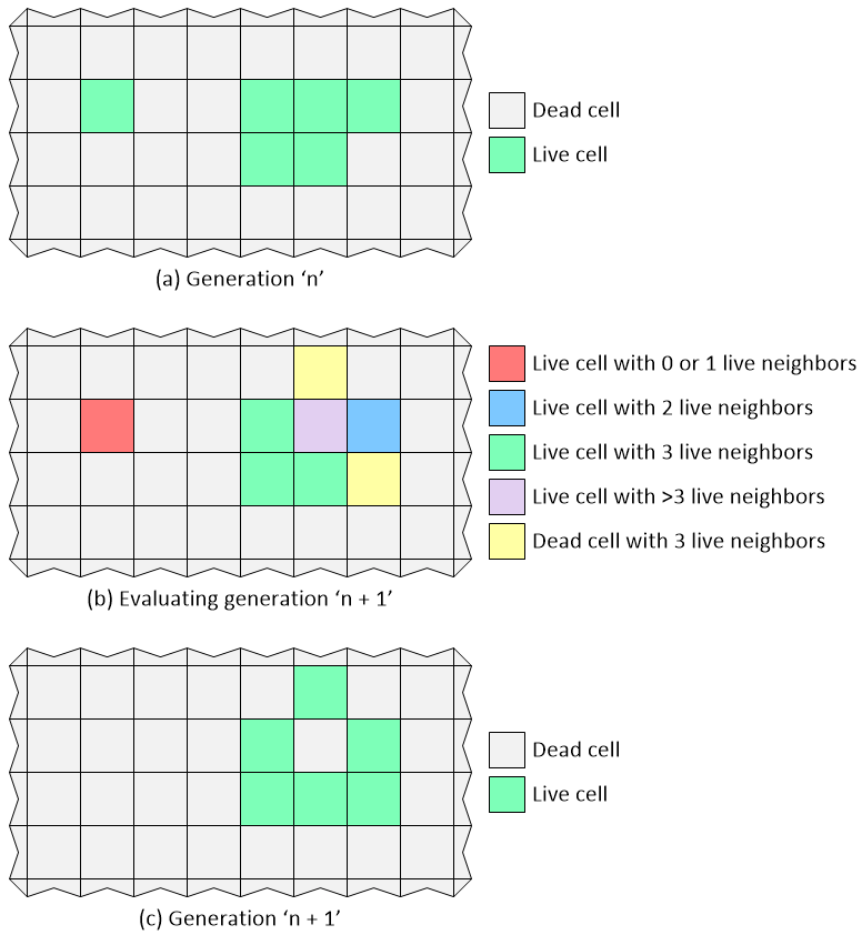
Graphical depiction of the game of life (Image source: Max Maxfield)
Purely for the sake of discussion, let’s assume that we have a small Game of Life universe that’s 100 x 100 cells in size. Let’s also assume we are using a microprocessor running at 50 MHz and that each of its instructions requires a single clock cycle. In this case, we will probably need to make two passes through the array to generate the new generation. The first pass will clunk along, row by row and column by column, calculating the number of live neighbors for each cell. The second pass will use this data to lumber along, row by row and column by column, to populate the new generation.
My “back of the envelope” calculations suggest that we will require around 50 operations per cell, which equates to 100 x 100 x 50 = 500,000 operations, which means we can process 100 generations per second. Well, that’s not too bad, is it? Now let’s suppose we wish our simulation to run for 100,000 generations. In this case, the entire simulation will take 100,000 / 100 = 1,000 seconds, or a little over 16 minutes.
By comparison, suppose we decide to use an FPGA to implement our Game of Life. The thing about FPGAs is that they can be used to perform operations in a massively parallel fashion. In the case of our Game of Life, for example, each cell could be implemented as an independent unit that could evaluate the live/dead states of its neighbors and react accordingly, and they could all do this simultaneously on each active clock edge.
If we assume that our FPGA sports the same 50 MHz clock as our microprocessor, then it can evaluate each generation in 1/50,000,000 of a second, so the 100,000 generations that took the microprocessor 16 minutes to calculate would take the FPGA 1/500th of a second. Looking at this another way, if we assume our display has a refresh rate of 100 Hz, then the cells in all 100,000 generations in our Game of Life universe would have lived, procreated, and died in 1/5th the time it would take to refresh our display even once. (See also What Are FPGAs and Why Are They Needed?)
It makes you think, doesn’t it?
Feel the (Radiation) Burn
Radiation comes in different flavors. On the one hand we have electromagnetic radiation (EM radiation or EMR), whose force carrier is a massless particle called a photon, which travels at the speed of light. EMR encompasses radio waves, microwaves, infrared, visible light, ultraviolet, X-rays, and gamma rays.
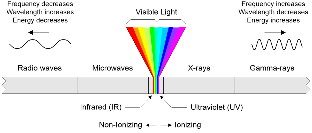
The electromagnetic spectrum (Image source: Max Maxfield)
If a photon has a frequency in the ultraviolet band or higher, when it hits an atom or a molecule, it can impart enough energy to strip away an electron from that atom or molecule, thereby leaving a positive ion. Thus, this is referred to as “ionizing radiation.”
The other form of radiation is based on particles like electrons (also known as beta particles), protons, neutrons, and atomic nuclei. In turn, the atomic nuclei range from helium nuclei (also known as alpha particles) to heavier ions. Once again, if one of these particles is traveling fast enough when it comes into contact with an atom or molecule, it can impart enough energy to strip away an electron from that atom or molecule, thereby leaving a positive ion.
There are all sorts of ways in which radiation can affect semiconductor devices, which are popularly known as “silicon chips.” Over time, for example, radiation can degrade the semiconductor’s crystal lattice. Also, it can cause electric charge to build up between the various layers forming the chip. The result can be to change the switching thresholds of transistors, increase leakage, increase power consumption, and reduce performance. For this reason, designers who intend to deploy semiconductor devices in hostile radiation environments are interested in something known as the total ionizing dose (TID), which refers to the amount of ionizing radiation the device is exposed to over time.
Another class of radiation effects, called single event effects (SEEs), provide more immediate results. A SEE refers to an effect resulting from a single ionizing particle (electron, proton, ion, photon…) that induces an immediate response in an integrated circuit.
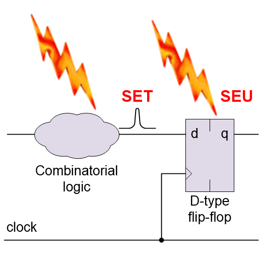
A single event upset (SEU) is a SEE that strikes a sensitive node in the circuit causing it to change state; for example, a register bit or a memory cell flipping from a 0 to a 1, or vice versa.
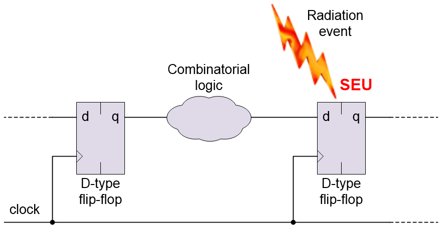
A single event upset (SEU) causing a register bit to flip (Source: Max Maxfield)
By comparison, a single event transient (SET) is a SEE that strikes a chunk of combinatorial logic resulting in a pulse, glitch, or spike.
![]()
A single event transient (SET) in the combinatorial logic (Source: Max Maxfield)
The problem arises when the SET is inadvertently loaded into a register or memory element, at which point it becomes a SEU. On the bright side, unlike the problems caused by the TID, an SEU is designated as being a “soft error” because it can be corrected (if you know what you are doing).
There are more potential problems, like the dreaded single event latch-up (SEL), multiple cell upsets (MCUs), and multiple bit upsets (MBUs), but we will save these little scamps for Part 2.
Pity the Poor FPGA
All silicon chips are susceptible to the effects of radiation. FPGAs experience a “double-whammy” because, in addition to their regular registers and memory cells that form part of the user’s design, they also contain configuration cells, which are used to configure the programmable fabric.
Some FPGAs are classed as being SRAM-based, which means their configuration cells are formed from SRAM cells. These devices are also classed as being volatile because their configuration is lost when power is removed from the system. In turn, this means their configuration has to be reloaded when power is first applied to the system. One major advantage of SRAM-based FPGAs is that they can be created using cutting-edge CMOS fabrication processes (other types of FPGAs require additional processing steps and typically lag the leading edge by one or two process generations).
Speaking of “other FPGAs,” some of these are classed as being flash-based, which means their configuration is stored in flash memory cells. In addition to the fact that these devices are “instant on” (i.e., they don’t require their configuration to be loaded from an external source), flash memory is less susceptible to the effects of radiation than is SRAM. Based on this, you might think flash-based FPGAs are the way to go in hostile radiation environments. But wait, there’s more, because — when power is first applied to the system — flash-based FPGAs typically copy the configuration stored in their flash configuration memory into SRAM-based configuration cells, which sort of means we’re back where we started.
Wouldn’t it be wonderful if we could create SRAM-based FPGAs using a process that is inherently resilient to the effects of radiation? Well, by golly, I was recently introduced to just such a process, which is … going to be the topic of my next column. Until then, as always, I welcome your comments and questions and suggestions.


