

Do you recall the 1963 American comedy film — It’s a Mad, Mad, Mad, Mad World — starring Spencer Tracy accompanied by an all-star cast of comedians, including Buddy Hackett, Ethel Merman, Mickey Rooney, Terry Thomas, and Phil Silvers? Well, that has nothing to do with what we’re going to talk about here.
In my previous column — CIRRENT Cloud ID Automates Cloud Certificate Provisioning and IoT Device-to-Cloud Authentication — I promised to bring us all up to date with the current state-of-play regarding our SMADs, where “SMAD” stands for “Steve and Max’s Awesome Displays” (hey, if you’ve got it, you should flaunt it LOL).
As a reminder to start the ball rolling, my chum Steve Manley (based in the UK) and your humble narrator (ensconced in the USA) are working on building 10-character versions of our 21-segment Victorian displays. The reason for the “Victorian” appellation is that the patent for the original version of these displays was first applied for in 1898, which places them firmly in the Victorian era (see also Recreating Retro-Futuristic 21-Segment Victorian Displays).
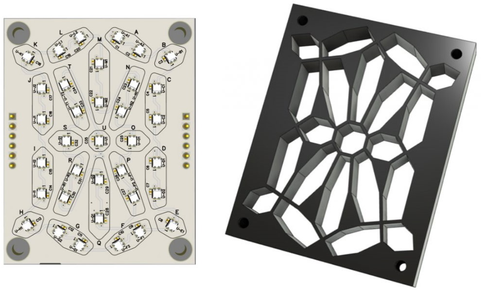
21-Segment Victorian Display: Board (left) and 3D printed shell (right)
(Image source: Steve Manley)
Attached to the front of each display board is a 10 mm thick 3D printed shell. In front of this we place a diffuser layer (we’re using pieces of the white plastic dividers intended for use as file-folder dividers). And, in front of the diffuser, we have a 1 mm thick facia (face plate) to hold everything in place.
Regarding the main shells, Steve experimented with different thicknesses before determining that 10 mm offered the ideal separation to provide maximum brightness while preventing the LEDs from appearing as points of light.
As seen in the image above, these displays each boast 35 tricolor WS2812 LEDs — the 7 smaller segments have only one LED, while the 14 larger segments have two LEDs each. Originally, we only ever considered driving each segment a single color, but we subsequently discovered that it’s possible to achieve some very interesting gradient effects by mixing two colors in the 2-LED segments, especially when dynamically transitioning from color-to-color as illustrated in this video.
Steve and I also collaborated on creating a cunning control board, a potent power distribution board, and a rather pert prototyping board to accompany our displays (if the truth be told, Steve did the bulk of the work while I bounced up and down offering (occasionally) useful suggestions).
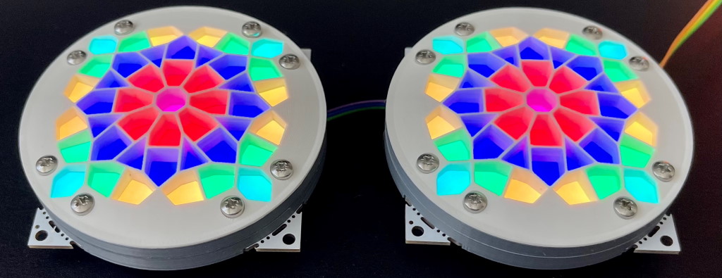
The thing is that I write a monthly Cool Beans column for Practical Electronics, which is the UK’s premier electronics, computing, and maker hobbyist magazine. I’ve mentioned the 10-character versions of our 21-segment displays in those columns, but this is a bit beyond what most readers are interested in creating themselves. This is why we came up with our SMAD concept, which involves an 80 x 80 mm board with 45 tricolor LEDs.
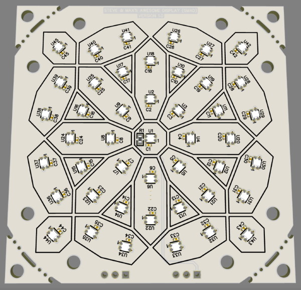
Front view of a SMAD board (Image source: Steve Manley)
The basic boards are square, but they are presented with break-off corners, which allows them to be used with circular shells, if required.
The way we originally considered using our SMADs was by equipping them with 29-segment shells, with 13 segments having only one LED and 16 segments having two LEDs each. But then Steve impetuously decided to experiment with 45-segment shells (each LED inhabits its own segment), which threw me into a bit of a quandary. On the one hand, I delight in the gradient effects we can achieve with the 2-LED segments provided by the 29-segment shells; on the other hand, I also drool over the “stained-glass” effects we can implement using the 45-segment shells.
As an aside, I was going to say that choosing between the two types of shells left me sitting on the horns of a dilemma. But that would be incorrect because this expression refers to having to choose between things that are unpleasant or undesirable, which doesn’t apply to our 29-segment versus 45-segment options, both of which are very desirable indeed. In case you were wondering, according to an entry I just found on The Free Dictionary: “A mid-16th-century source described a dilemma as ‘a horned argument’ (after the Latin argumentum cornutum), the idea being that if you avoided one ‘horn’ of the argument you ended up impaled on the other.” But we digress…
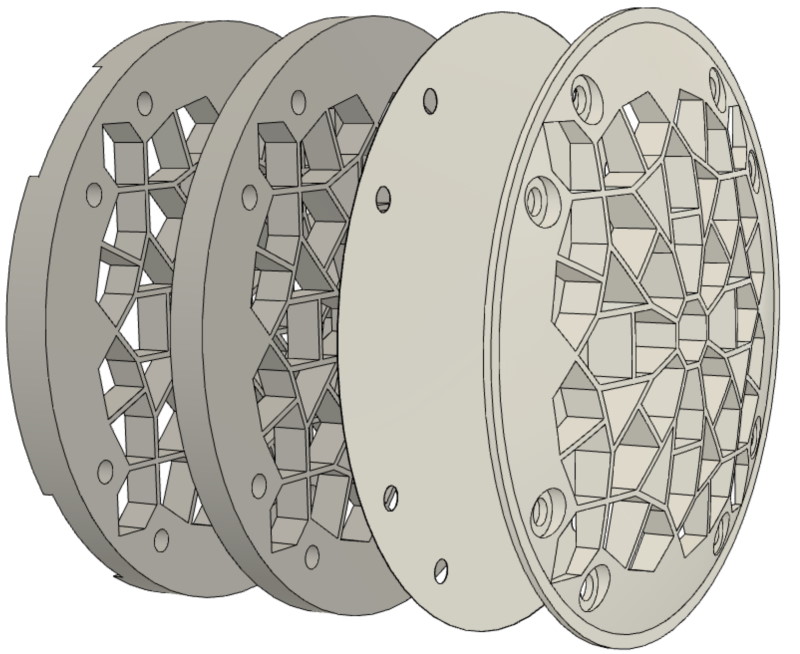
Feast your orbs on the image below, which depicts the difference between 45-segment and 29-segment SMAD assemblies. In each case, from left to right, we have the circuit board, the shell, the diffuser, and the facia.
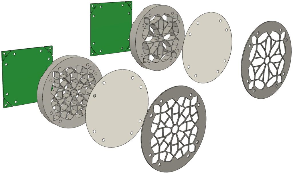
Comparison of a 45-segment SMAD assembly (left) and a 29-segment SMAD assembly (right)
(Image source: Steve Manley)
For your delectation and delight, Steve created this video comparing a bare SMAD (left), a SMAD with a 29-segment shell (middle), and a SMAD with a 45-segment shell (right).
There are several great things about SMADs — especially with respect to my writing about them in publications like Practical Electronics — including being relatively inexpensive, being controllable using a single pin from a cheap-and-cheerful microcontroller — like an 8-bit Arduino Uno or a 32-bit XIAO (see Say Hello to the Seeedunio XIAO) — and the fact that you can have “fun with just wun” (Shakespeare I ain’t).
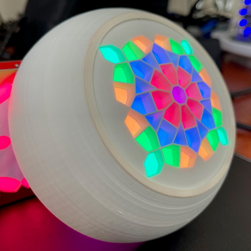
Of course, if one is good, two are better, because you can never have too many LEDs (or SMADs) in your life. In my case, I decided to create two pseudo robot heads, each with two SMAD eyes. The head shown below is equipped with 45-segment shells, while my other head flaunts 29-segment shells (this video shows them “talking” to each other using Morse code).
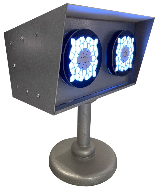
A pseudo robot head equipped with two 45-segment SMAD eyes
(Image source: Max Maxfield)
I don’t know about you, but I think my head looks rather spiffy. I also like my pseudo robot head. I turned the base and the column on a lathe in the workshop of my friend Carpenter Bob; the main platform and the front panel are 3/16” plywood, while the sides and top are simply thick card. Meanwhile, the bolts on the side are just for show (hot glue is my friend).
The reason I use the “pseudo” qualifier is that my robot heads don’t move. The only things that actually do anything are the SMADs, but all of that is about to change because the editor of Practical Electronics asked if I could add some motion capability to my robot heads
There’s nothing I can do with my existing heads, but I’ve started work on a new version. Initially, I’m just going to be playing with a quick-and-dirty solution using two small servo-driven pan-and-tilt mechanisms from Adafruit. In turn, these will allow me to experiment with two 4-Axis Joysticks I picked up on eBay (in reality, these are only 3-axis — forward/backward, left/right, clockwise/anticlockwise — with a pushbutton on top, but even so they are super spiffy).
Using these joysticks in conjunction with my pan-and-tilt mechanisms will allow me to individually control each eye’s up-down-left-right motions. Meanwhile, as illustrated below, Steve has 3D-printed some new curved facias that bulge out to be 5 mm thick in the center.
SMAD shell with 45-segment curved facia
(Image source: Steve Manley)
We tried heat-wrapping the diffuser over the curved (outer) face of the facia, but that was a disaster, so we decided to stick with having the diffuser sandwiched between the main shell and the facia. The reason the main shell is shown as being split into two 5 mm-thick slices is because this makes them easier to paint (we print them in gray plastic to limit light bleed, then paint the insides of the segments white to boost their brightness). The result is rather spectacular as shown below.
SMAD shells with 45-segment curved facias
(Image source: Steve Manley)
Do you recall my recent column — Mega-Cool Laser-Based Sub-Jellybean-Sized Multizone Ranging Sensor — in which I introduced the new VL53L5CX Time-of-Flight 8×8 Multizone Ranging Sensor from STMicroelectronics? Well, I’m also thinking about equipping my new robot head with one of these sensors so that it can track my gestures and respond appropriately.
But the super exciting news is that Steve has leapt into action with respect to creating a much more sophisticated version of our robot head. In addition to having pan-and-tilt capability for the SMAD eyes, Steve is going to implement the same capability for the whole head. Steve and I both invested in the same type of 4-axis joysticks, which means that — when we have our heads in our hands, as it were — we’ll be able to use one joystick to control the robot’s neck and the other to direct its SMAD eyes.
Take a look at this recent video showing Steve’s servo-controlled eyes in motion. This shows only the frame holding the eyes, all of which is attached to a piece of wood because the full-up neck assembly is still a work in progress. Just for giggles and grins, Steve has the colors of the eyes responding to sound.
I cannot wait to show all of this to you in more detail, because Steve has implemented his servo-eye assemblies in a way I’ve never seen done before.
Once we have the fully articulated heads with their fully articulated SMAD eyes, we’re going to look into adding additional sensor capabilities, such as facial recognition and expression recognition, but all that will be a story for another day. In the meantime, as always, I welcome your comments, questions, and suggestions.


