

I’m a big fan of having hobby projects. In addition to taking one’s mind off the toils, troubles, and tribulations of the world, I think that having a new “thing” that you want to do is the best way to set about learning how to do it.
Take adding a new programming language to your repertoire as an example. One way to do this is to wade through the language reference manual (yawn). Another approach is to come up with some algorithm or task you wish to code in this new language, and then research how to achieve this goal. Of course, I’m not saying that reading the language reference manual is a bad idea, just that it’s not the only instrument in the toolbox.
Recently, my chum Adam Taylor and I wrote a trio, troika, or triad of columns under the umbrella topic of “How to Get an Engineering Job and Keep It.” In Part 1, we focused on the precursor days at high school, college, and university leading to a career in engineering. In Part 2, we pondered the creation of a resume (a.k.a. curriculum vitae, commonly referred to as a CV) and the joys of being interviewed. In Part 3, we cogitated and ruminated on how one can keep one’s job, grow in it, and evolve one’s career.
As part of this, we asked our engineering friends to share their thoughts, and it was surprising how often the topic of hobby projects came into the conversation. If someone is going for their first job interview, for example, then they may have limited previous work experience to which they can point, but they can always talk about the hobby projects they’ve created and the things they’ve learned while doing so. In fact, one of the guys said that when he was starting out back in the day (circa the 1970s), he used to take a portfolio of photographs showing the things he’d created, which helped to differentiate him from other contenders for the position.
Personally, I’ve habitually got a number of hobby projects on the go (one day, I hope to actually finish one or more of the little rascals). Many of these little beauties have a steampunk look and feel because I’m a big fan of the anachronistic retro-futuristic steampunk aesthetic (try saying that ten times quickly).
As one example, I based my Awesome Audio-Reactive Artifact on a small, cheap-and-cheerful, pseudo-antique decorative valise with a hint of a sniff of a whiff of steampunk about it. First, I took a bunch of defunct vacuum tubes and cut the pins off their bottoms. Next, I painted a piece of 3/16” plywood matt black, drilled holes into it, and attached the tubes with epoxy. Underneath the tubes I attached 145 tricolor LEDs in the form of WS2812B devices (a.k.a. NeoPixels). I then added a microphone, a simple audio spectrum analyzer chip, and an Arduino Uno. When this artifact is responding to ambient sounds or music, anyone who casts their orbs on this little beauty invariably says “Ooh” or “Aah” (sometimes both, but not at the same time).
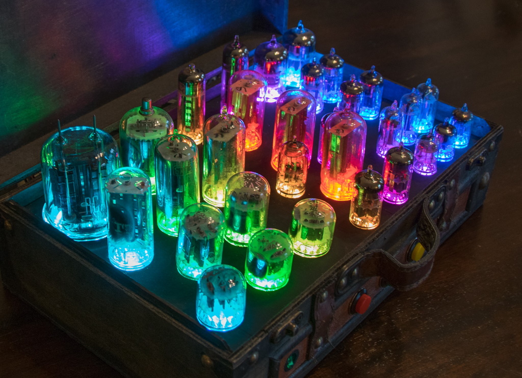
Meet my Awesome Audio-Reactive Artifact (Image source: Max Maxfield)
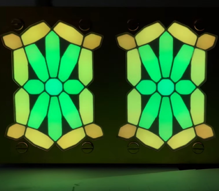
All of which leads to my current project, which is based — believe it or not — on modern interpretations of 21-segment displays that were conceived in the days when Queen Victoria was the ruler of all she surveyed.
This all came about when two friends of mine — Paul Parry (owner of Bad Dog Designs) and Steve Manley ran across a group called Smartsockets. As it says on the group’s website, “Smartsockets are a software and hardware system for driving multi-segment alphanumeric displays. Originally intended for nixie tubes, versions have also been adapted for VFD tubes and LEDs. Smartsockets are versatile device-specific controllers which are designed to make implementations of multiple element visual displays simple to create.”
As I understand it, one of the moderators of the group, John Smout, ran across this patent for a 21-segment display that was filed by George Lafayette Mason in 1898, which is 123 years ago as I pen these words. The original displays employed 21 small incandescent bulbs — one per segment — which were controlled by a complicated electromechanical switch that activated groups of segments as required to represent the different characters.
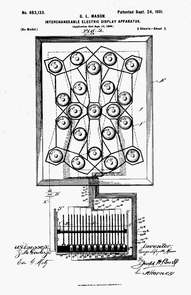
Image from George Lafayette Mason’s original patent application.
The folks in the Smartsocket group plan on creating their own versions of these displays using a variety of technologies. The main point regarding their implementation is that each display will have its own PIC microcontroller, which is where the “Smart” portion of the Smartsocket moniker originates. By comparison, Paul, Steve, and yours truly prefer to drive our displays using a single Arduino-compatible microcontroller. As a result, the two groups have diverged implementation-wise, although everyone keeps everyone else in touch with what’s going on.
Steve, in particular, has done some sterling work with regard to creating 3D models from which we can use 3D printers to create “shells” to house the displays, and also to create a printed circuit board (PCB) that boasts 35 tricolor WS2812B LEDs. Each character is 50 mm wide by 64 mm tall. A couple of months ago, Steve created an in-depth video illustrating various experiments and everything he had achieved up to that time.
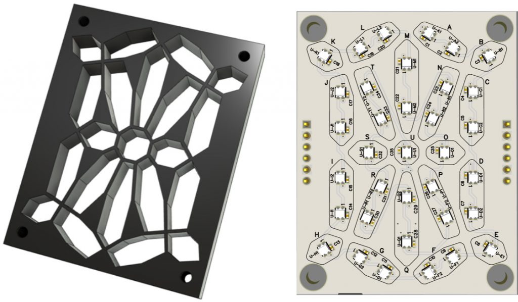
3D shell and circuit board (Image source: Steve Manley)
Steve was kind enough to supply me with 10 of the PCBs and the design files for me to 3D print 10 shells so that I can build my own 10-character display. The reason I opted for ten characters was that I saw an interesting article and video from 2007 showing a piece of word art created by Matt Gorbett that was based on a V1 Smartsocket implementation.
Matt’s idea was that people passing by could use the four potentiometers to specify the missing 4-letter word in the “I **** YOU” phrase. After a while, the system will start swapping individual letters in this 4-letter word to generate thought-provoking alternatives.
I loved this concept, but I didn’t want to restrict myself, so I decided to have a potentiometer associated with each of my characters. Also, Steve and I both like the look of brass panels, so he whipped up some 3D models as shown below.
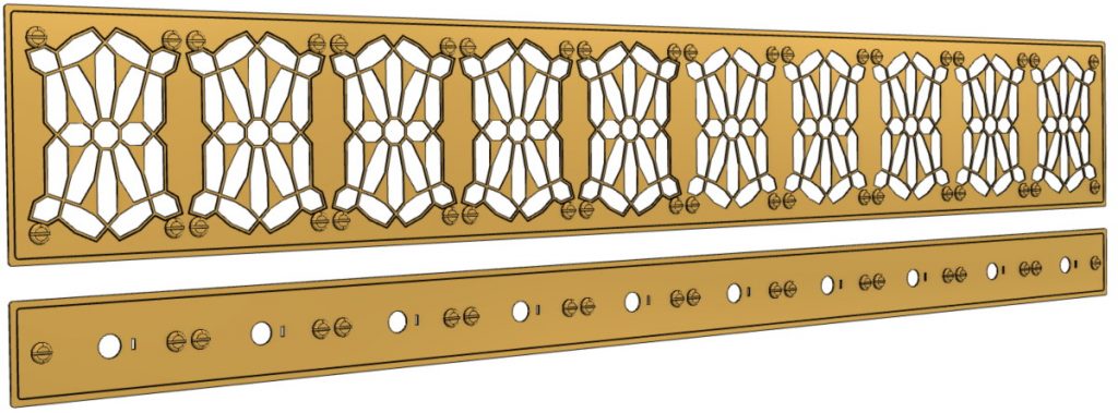
3D models of brass plates for use with our 10-character displays (Image source: Steve Manley)
To be honest, I wasn’t sure if we were going to be able to implement these panels because the strips between adjacent segment faces are only 0.7 mm wide. Fortunately, my chum Kevin McIntosh (owner of The Laser Hut) has a huge laser, although he’s not one to boast and — as we all know — it’s not the size of your laser but how you wield it that counts. Anyway, Kevin successfully cut some pseudo-brass panels out of acrylic for us that are so audaciously awesome that they bring a little tear (of joy) to my eye.
In addition to displaying text messages, these displays can be used to present a captivating light show. We could even make the display react to sound in a similar manner to the Audio-Reactive Artifact we discussed at the beginning of this column.
With regard to the circuit board shown earlier, did you spot the fact that some of the segments boast two tricolor LEDs? Well, this made me think that we could visualize the LEDs as forming rings and use these rings to display ripples of light radiating from, or converging on, the center. Such an effect could find multiple uses, including transitioning from one phrase to another. After I sketched this out, I talked to Steve, but it turned out he was ahead of me. On the other hand, we soon discovered that we had come up with slightly different implementations as shown below.
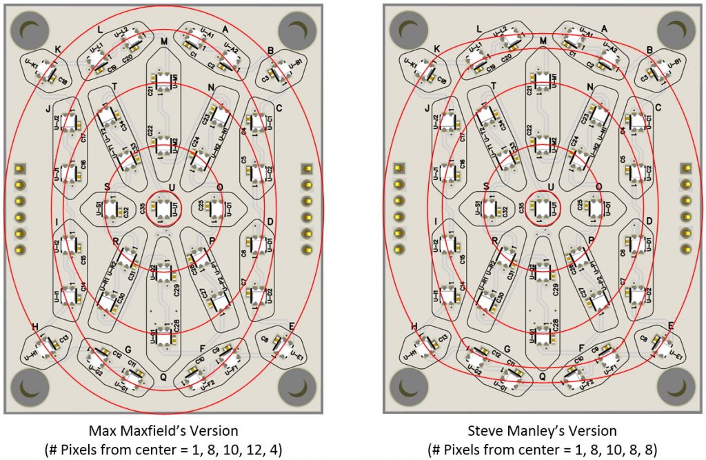
Alternative ways of defining rings of LEDs (Image source: Max Maxfield)
Since I’m still in the process of constructing my display, Steve ran a quick test as shown in this video. Steve tells me that there is a subtle difference between these implementations in the real-world that’s not immediately apparent in the video. I can’t wait to create my own tests and see this with my own eyes.
Speaking of seeing things with my own eyes. One of the problems Steve and I have run across when we’ve created our own incarnations of similar projects in the past is that we’ve each gone our own way with regard to microprocessors, real-time clocks (RTCs), audio codecs, and so forth. The main downside to this is that we haven’t been able to easily share code back and forth. It would be much more efficacious if we were in a position to create new effects and could share them and see them in action.
In order to facilitate this, we are working on creating a common controller board. When I say “we,” Steve has done the bulk of the work, with me offering the occasional (hopefully useful) suggestion. For example, with his original test rig, Steve started off by driving all of his digits using a single buffered pin on a Teensy-LC (32-bit 48 MHz Arm Cortex-M0+ with 62 KB Flash and 8 KB RAM) from PRJC Electronics. Since our displays have 10 characters, each with 35 NeoPixels, that means a total of 350 NeoPixels, which requires around 11 ms (milliseconds) to upload. If we assume an additional 9 ms to perform any calculations, this results in a total of 20 ms per cycle, which limits the refresh rate to 50 Hz.
Is this good enough? Probably. Are we satisfied with “good enough”? Certainly not! Thus, I campaigned vigorously for us to use either a Teensy 3.2 microcontroller (32-bit 72 MHz Arm Cortex-M4 with 256 KB Flash and 64 KB RAM) or a Teensy 3.6 microcontroller (32-bit 180 MHz Arm Cortex-M4 with 1 MB Flash and 256 KB RAM). Both of these little scamps support PRJC’s Octo Library, which allows eight strings of WS2812 LEDs to be loaded simultaneously. In my case, I prefer the Teensy 3.6 because — in addition to its higher clock speed and larger memory — it boasts a cornucopia of analog and digital input/output (I/O) pins.
If we use five strings, each driving two characters (70 LEDs), then the upload time is reduced to a tad over 2 ms. Even better, the upload using the Octo library is performed using an on-chip direct memory access (DMA) engine, which works in the background, leaving the processor free to carry on cogitating on its calculations. As a result, this boosts our maximum refresh rate to a whopping (theoretical) 500 Hz. Ooh — Shiny! (In practice, we are planning on using a 100 Hz refresh rate.)
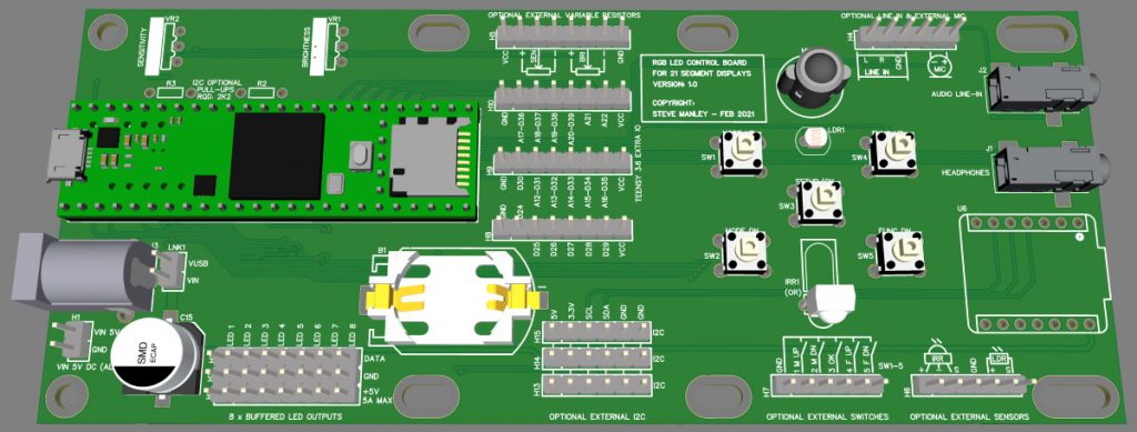
3D Model of new control board (Image source: Steve Manley)
Also, observe the five momentary push button switches, which we will use to perform tasks like setting the real-time clock and controlling the various display modes. There are also header pins that will allow five more switches to be connected in parallel, where these additional “outward-facing” switches may be mounted on the cabinet.
As you may recall, I wrote a 9-part series on the Ultimate Guide to Switch Debounce, so I immediately asked Steve how he was planning on debouncing his switches. Eeek! It turns out he was using the old, “Wait for the first active edge — then wait for 30 ms to see if the switch is still pressed — if so, do whatever it is we want to do — finally, enter a tight loop (thereby preventing anything else from taking place) waiting for the switch to be released” approach. I immediately suggested that we add a 6-channel LS119-S switch debounce IC from LogiSwitch. In addition to removing any switch bounce, this device also boasts a unique single-wire handshake protocol, which allows the microcontroller to clear the switch event and move on to more important things (see the Ultimate Guide to Switch Debounce: Part 6).
There’s far too much to go into here. Suffice it to say that this control board is designed to mount on the back of the display spanning three character “slots.” It will accept either a Teensy 3.2 or 3.6. It boasts a real-time clock and back-up battery, and one can optionally add an audio codec chip for sound, along with a Seeeduino XIAO processor to handle communications from an infrared controller (the location for the XIAO is on the right-hand edge of the board).
It probably goes without saying that the boards Steve and I use for this project will be fully loaded. The reason for the various options is that this board will be able to drive multiple projects in the future, and those projects may not require all of these capabilities. On the other hand, some future projects may require extra features and functions. Thus, in addition to a separate power distribution board, Steve is also working on a prototyping board with an enhanced breadboard footprint / wiring scheme.
The image below shows mockups of the three boards printed on card and attached to the back of one of Steve’s early displays. From left to right we see the power distribution board (occupying one “slot”), the main control board (three “slots”), and the prototyping board (four “slots”). The reason I say “early displays” is that this image shows ten of the original 3D printed shells, which are the ones I have. Steve subsequently created new shells for his latest display. These updated shells are a little wider, thereby providing a slightly larger gap between characters, which Steve deems to be aesthetically more pleasing. This also explains why some of the attachment holes on the boards are presented as elongated slots, thereby allowing the boards to be attached to displays created using Steve’s new shells and my older versions.
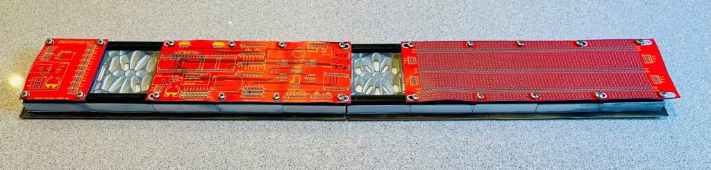
Mockups of the three boards attached to the back of an old display (Image source: Steve Manley)
I already have ideas for the prototyping board. For example, in my column on Getting Started with MEMS-Based Motion and Orientation Sensors, I introduced the 9DOF Fusion Breakout Board (BOB) from Adafruit. This BOB features the BNO055 sensor from Bosch. In addition to a 3-axis accelerometer, a 3-axis-gyroscope, and a 3-axis magnetometer, the BNO055 also includes a 32-bit Arm Cortex-M0+, which performs sensor fusion and presents you with data in a form you can use without your brains leaking out of your ears.
In fact, as you can see in this video, I already added one of these sensors to my 12×12 ping pong ball array, where it’s used to allow me to “roll” a pixel around the array by simply tilting the array. The reason I mention this here is that I’m planning on adding one of these sensors to the prototyping board in my 10-character 21-segment Victorian display, thereby letting me do things like “sliding” text messages in and out by simply tilting the display.
I fear I may have outstayed my welcome in this column by waffling on too long, although I’ve really only touched on the myriad topics I wanted to talk about. So, I’m going to leave this up to you. If you would like to hear more about the progress of this project in future columns, speak now (post a comment) or forever hold your peace. Unless someone (the more the merrier) says, “Yes please, I would dearly love to stay informed about this amazing project,” then my lips will remain sealed. So, what say you?


I do like this these Victorian/steam punk type projects. Shame Mr Mason isn’t around today to see his ideas being used in the 21st century, and I approve of the way he drew his battery and labelled the positive/negative terminals on the patent. His way always made more sense to me.
Keep up the good work Max and keep us informed how you get on.
Thanks UK Joe — I just needed one person to encourage me (open the floodgates LOL)
can’t figure out if it’s choice or compulsion, but always have something on the go myself ( also even finish some of them )
by all means, hoard not the splendour and the glory
“…also even finish some of them…” Now you are just showing off LOL