

There’s no more fundamental piece of test gear for electrical engineers than a multimeter. I own a bunch, starting with my Micronta 22-150 analog multimeter with a mirrored scale, which I bought from Radio Shack in my high school days back in the 1970s. Miraculously, that meter still works. I’ve got at least five Cen-Tech 3½-digit Digital Multimeters that Harbor Freight used to give away for free with a coupon. (That’s about what they’re worth.) These meters are slow and have relatively low resolution, but they’re fine for monitoring multiple power supply voltages. I’ve got my trusty 3½-digit Fluke 77 handheld multimeter, which I’ve owned since the 1980s. Fluke introduced that meter in 1983, and it’s always been a rock for me. A few years back, I bought a Surpeer AV4 for just $40 from Amazon with free shipping. It’s a 20,000-count handheld meter, and it seemed surprisingly accurate for such a cheap meter when I checked it against a recently calibrated Agilent 34401 benchtop DVM. (See “Is a $6.99, Tilswall 6000-count Multimeter from Amazon a Tool or a Toy?”)
So, I do not lack for multimeters, but I got a certain type of itch when watching the many instrument repair videos on my favorite YouTube electronics channels: EEVblog by Dave Jones, CuriousMarc by Marc Verdiell, Mr. Carlson’s Lab by Paul Carlson, The Signal Path by Shahriar Shahramian, Marco Reps, etc. These YouTube channels show successful resuscitations for all sorts of old electronic test gear and explain the repairs in great detail. I felt the need to do likewise, but here in EEJournal instead of YouTube, so I searched eBay and found a listing for a non-working Keithley Model 179 multimeter. It called out to me. The dead meter had a $20 buy-it-now price with another $20 and change for shipping. I thought that I just might be able to repair this venerable 4½-digit multimeter from a storied instrument maker and put it back in service, so I clicked the “Buy It Now” button and waited for the package to arrive.
Joseph Keithley founded Keithley Instruments in 1946. He’d earned an MSEE from MIT in 1937, then worked for Bell Telephone Laboratories in the late 1930s, served at the US Naval Ordnance Laboratory during World War II, and took a job with Massa Labs in Cleveland after the war ended. When Massa left Cleveland in 1946, Keithley stayed and founded his own company. The company developed a few products and introduced its first meter in 1950: a high-impedance DC voltmeter called the Model 200. The Model 200 proved useful in testing insulation resistance, and Keithly eventually produced a line of electrometers, microvolt meters, nanovoltmeters, and picoammeters. The company developed a name for creating specialized instruments that could measure very small signals. When I went to Cleveland to get my BSEE degree at Case Western Reserve University, Keithley was a well-known instrument maker, at least regionally.
Keithley introduced the Model 179 digital multimeter in 1978. That was the era of LED readouts and pushbutton meters. My eBay meter has ICs with date codes from late 1981, so it was built three years after the meter’s introduction. This meter is based on a widely used Intersil chipset consisting of a digital CMOS ICL71C03 “Precision 4½ Digit A/D Converter” and the companion ICL8052 analog chip that contains a voltage reference and three op amps for the A/D converter’s dual-slope integrator. These two chips are still easily obtained, so I was confident that I’d be able to revive this meter.
Semiconductors are not the major failure mechanism for meters of this era. It’s the ganged pushbutton switch that is most often the culprit. These complex electromechanical switches permeate the design of multimeters from this era. The switch bank taps the meter’s main voltage divider, selects the proper voltage reference, switches in the true-RMS converter for measuring AC signals, and even routes signals to the display’s negative sign where needed. These pushbutton switches supplanted multi-wafer rotary switches, which were popular in the 1950s and 1960s. Compared to the rotary switches, the pushbutton switch banks are smaller, need less front-panel space, and permit more compact instrument designs. The design of these complex pushbutton switch banks is a lost art these days. Today, we let microprocessors do all of that switching for us. As they say, it’s just a matter of software.
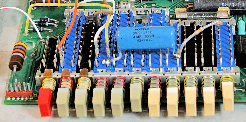
Developing gang pushbutton switches like this one in the Keithley Model 179 digital multimeter is now a lost art. Image credit: Steve Leibson
When my eBay meter arrived, I unpacked it and cracked the case open to see if there was any apparent damage or blown components. I’ve had instruments arrive with formerly socketed components rolling around inside of the instrument. It’s always a good idea to look for swollen electrolytic capacitors or burned tantalum capacitors before applying power. My Model 179 arrived in excellent cosmetic shape. It had no loose components or sketchy looking capacitors inside, so I plugged it in, turned it on, and waited to hear a pop from an exploding capacitor. Instead, the multimeter’s LED display lit with a satisfying ruby red glow, but the readings changed randomly no matter what I did with the pushbutton switches on the front panel.
The first step was to clean the meter’s switches. I sprayed a liberal amount of CRC contact cleaner into the back of the switch bank and let it dry. When I switched the meter back on after one switch cleaning, the readings were just as random. People who’ve documented repairs to this meter, especially on the EEVblog Forum, have written that it has taken them as many as four cleanings to get these switches working properly. I tilted the meter’s main circuit board up against a support, put a paper towel beneath the switches to catch the drippings, and gave the switch bank a second drowning with contact cleaner. Discolored cleaning liquid with black specks oozed into the paper towel. After the fourth drowning, the cleaning fluid drained clear, so I figured the switch bank was now clean, or at least clean enough.
However, the switch cleaning had caused another problem. The switches had gone stiff. Normally, if you press one range button, the other four will pop out, thanks to integrated springs and a mechanical linkage between ganged pushbuttons. That was no longer happening on my meter after the cleaning. A bit of Internet searching indicated that the switch bank would need some oiling after cleaning to free up the mechanical mechanisms. I don’t have a needle oiler, so I sucked up some 3-in-1 oil into a hypodermic syringe with a flat needle and carefully injected drops of oil into small holes at the front of the switch bank. The oil freed up the mechanical linkages, and the buttons started to work properly after I exercised them a few times.
For added insurance on the switch contacts, I dripped a little Cramolin Blue contact conditioner into the switches. I’ve had a small vial of this contact conditioner since the mid-1980s when I wrote an article on snake oil contact cleaners. Cramolin is definitely the real deal. It’s not snake oil. I still have most of the Cramolin Blue vial’s contents along with a vial of the more aggressive Cramolin Red. Today, Cramolin goes under the name DeoxIT, but it’s still available. A little of this stuff goes a long way. In addition, one of the range-switching pushbutton keycaps had loosened when I pulled it free to clean it, so I applied a couple of drops of cyanoacrylate inside of the keycap and let the glue dry. After that, I plugged the cap back onto the switch and it fit nice and tight.
I reassembled the meter and switched it on. The display was still random. How disheartening! Time to probe around with fingers. Now, probing around in this meter is somewhat riskier than with more modern equipment. This meter has a single-board design, and the ac power supply sits on the same board with the other electronics. There’s a live, unguarded, 110-volt fuse holder with exposed contacts just inches away from the meter’s analog and digital circuitry. You’d never get away with that kind of design today. Caution is advised.
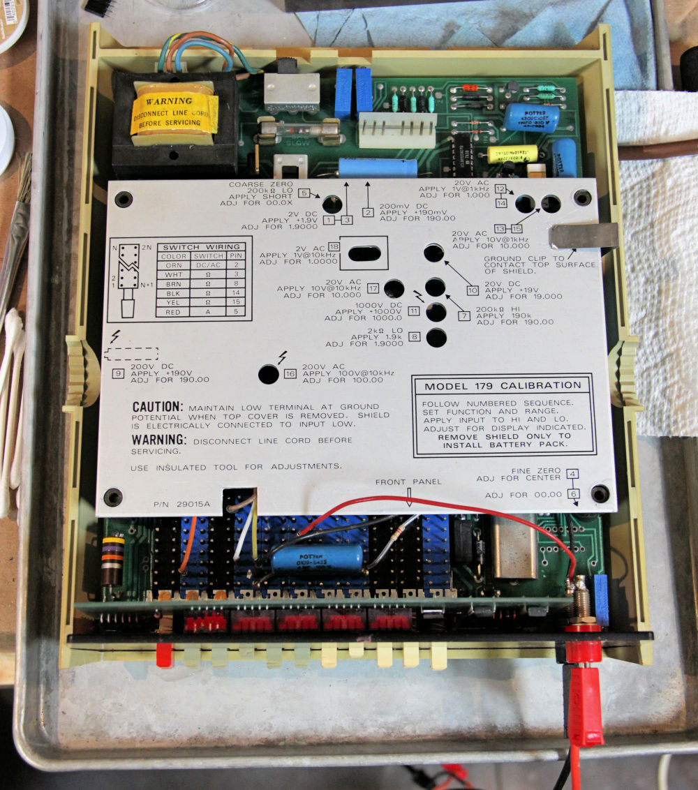
The Keithley Model 179 multimeter has a convenient calibration sequence printed on its electrostatic shield cover and a deadly exposed ac line fuse in the upper left part of the photo. Image credit: Steve Leibson
When I touched the display daughterboard, the meter’s display suddenly stabilized. Pushing the display board back and forth with my finger caused the display to go random or stable, depending on the board’s angle with respect to the main board. Obviously, there was a squirrely connection between the main board and the display board. That connection was made by a 6-pin and 11-pin set of connectors molded with mud-brown plastic housings. I recognized these connectors immediately, having used them at HP for board-to-board connections in my interface card designs back in the late 1970s, the same era that produced the Keithley Model 179. These connectors were made by Molex. I can’t think of another connector manufacturer that has used that muddy brown color. The connectors were in bad shape, as you can see in the image below. Cramolin wasn’t going to fix this problem.
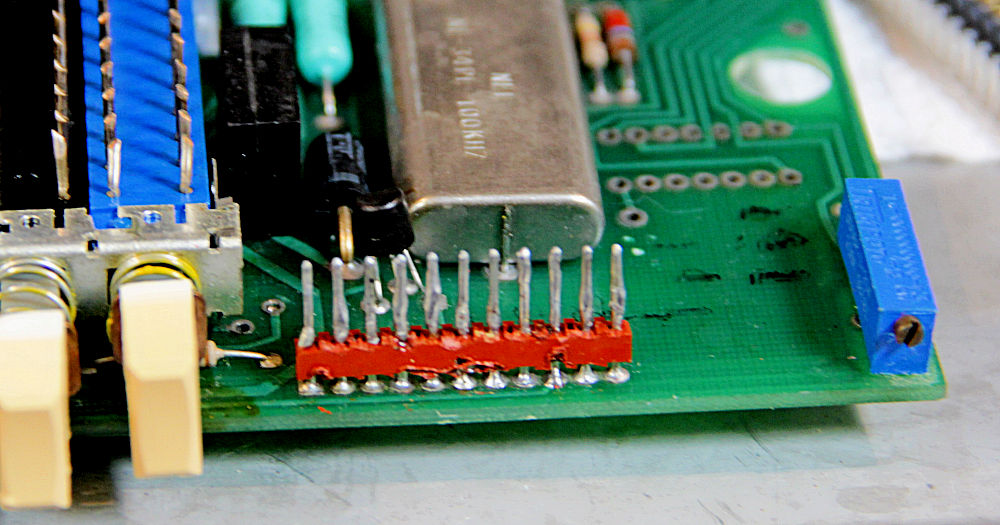
These board-to-board connector pins shouldn’t be covered in solder. Image credit: Steve Leibson
When I pried the meter’s display board from the main board, the situation was ugly. Someone had liberally applied an uneven coating of solder to the connecting pins in an attempt to widen them and fix the intermittent connection. This “fix” had obviously compromised the spring fingers in the female connector. That also explained the obvious bodge wire I’d found running from the main board to the display board, which replicated the function of one pin in the 6-pin display connector. Apparently, that pin didn’t respond well to the extra solder globbed onto the pins, so one of the previous owners of this instrument bypassed the one connector pin with the extra wire. I concluded that the only reasonable solution was to change out the female connectors on the display board and the mating pins on the main board.
The appropriate Molex connectors are still available. I’d need one 6-pin, right-angle female connector and one 11-pin, right angle female connector, along with some straight 0.100-inch pins. Instead, I elected to order snappable, right-angle male and straight female connectors from Amazon, because I could get them quickly and inexpensively. Free shipping doesn’t hurt either. I would flip the connectors and put the right-angle male pins on the display board and the straight female connectors on the main board. Newer Keithley multimeters also made this same connector design change.
When the replacement connectors arrived two days later, I started reworking the boards. While desoldering the connectors with my half-century-old, pre-SMT Weller soldering iron, I made two discoveries about these 40-year-old pc boards. First, the boards’ solder mask had become brittle over the years and would easily flake off in some places. The loss of solder mask meant I needed to be extra careful when soldering the new connectors so as not to create shorts. You can order UV-curable goop to repair solder masks these days, but I’d reached the end of my patience for ordering parts and products to fix this multimeter and pushed on. Fortunately, these 1970s-era pc boards only routed one trace between 0.100-inch pins, so it was not too difficult to avoid creating shorts when soldering. I just needed to be a bit careful.
Second, I discovered that the board’s copper traces could not take as much heat as I would normally expect. They would easily delaminate if overheated. I’m guessing the adhesive that bonds the copper to the FR4 board had gotten old just like the solder mask. There are several documented cases of traces lifting on these old Keithley meters.
Unfortunately, you need a fair amount of heat to desolder a multipin connector, so a couple of the connector pads on both the main and display boards delaminated. When I installed the new connectors, I was careful to make sure the circuit pads were tight against the board before soldering the pins in place. While I had my soldering iron warmed up, I also repaired the black lead wire that connected a pin on the switch bank to the meter’s negative input terminal. It had broken free. It took only seconds to make that repair.
I snapped the reworked display board to the main board and then tested continuity between the mated connectors on the main and display boards. There were no shorts, and all the connections were continuous, even when I wiggled the display board. All that remained was to power up the multimeter to see if I’d fixed the instrument.
The first time I switched the multimeter on after the rework, it didn’t power on properly – bummer! – so I buttoned it up and decided to think for a bit. I couldn’t think of anything, so I tried again to gather more data, but the multimeter powered up properly. This intermittent start-up problem has diminished as I’ve used the meter and disappeared entirely after a day or so, so I suspect there may be a capacitor in the power supply that caused a power-supply sequencing problem. Electrolytic capacitors can reform after being energized after a long dormant period, and I think that’s the case here.
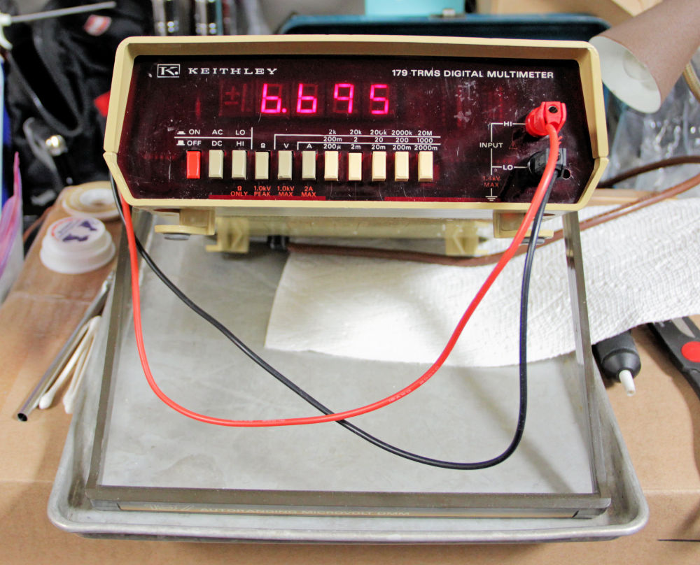
Yes, it works, finally. Image credit: Steve Leibson
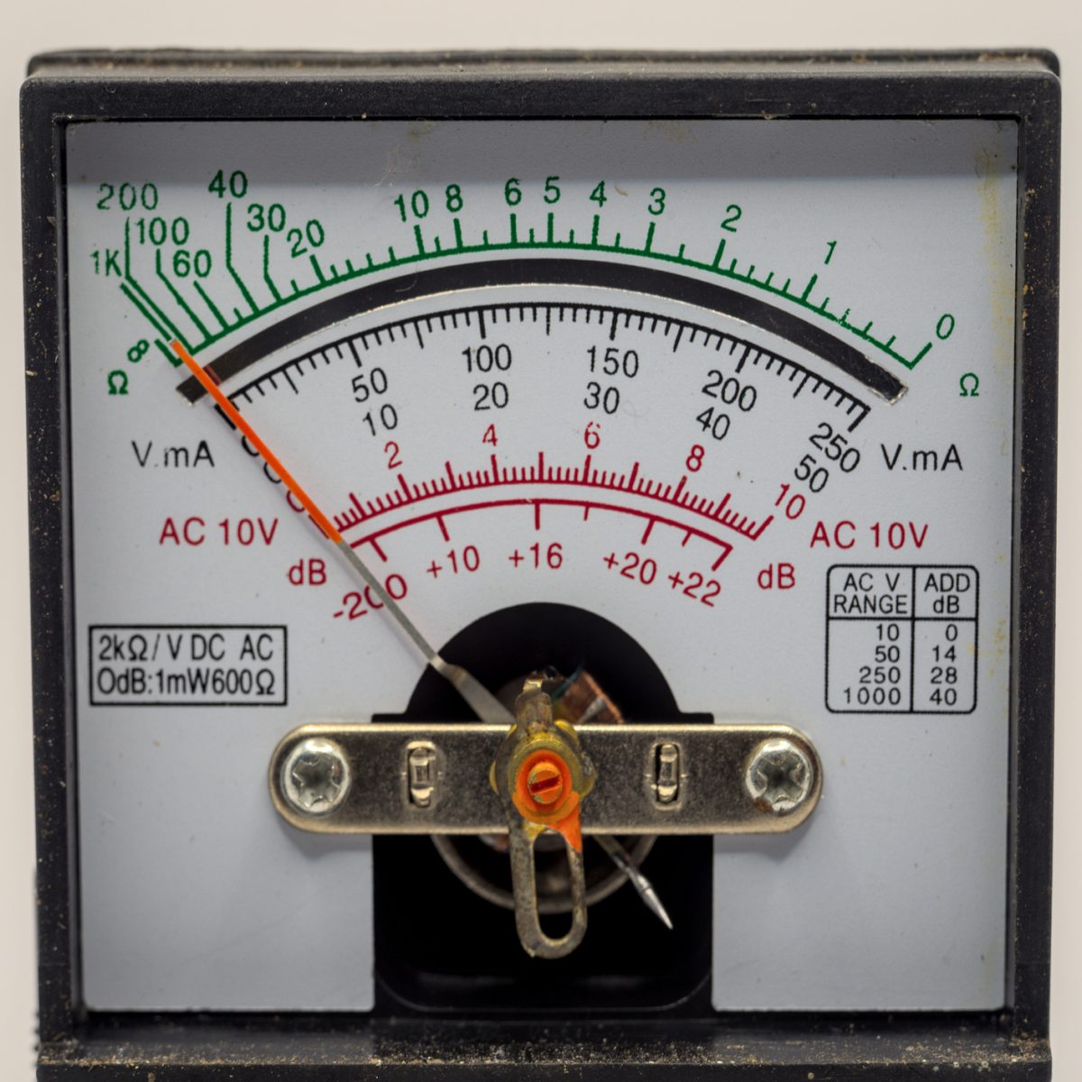
With the meter working, I measured a dc voltage from a power supply and compared the Keithley 179’s reading with the power supply’s analog voltage meter. The readings were incredibly close, which was very encouraging. I also reversed the lead polarity to check for a zero-offset problem, and there wasn’t one.
My next step was to verify the meter’s calibration. Because I saw no calibration stickers, I doubt that this meter had been calibrated at any time during this century, and possibly not since it left the factory in Cleveland forty years ago. I checked the Keithley 179 against my Surpeer AV4 multimeter, which had closely tracked an Agilent 34401 lab-grade meter when I checked it five years ago. The voltage scales seemed to work well. Next, I found a random 6.68K resistor and measured it with both the Keithley and the Surpeer meters. I then combined the resistor with a voltage to make a current source. (I didn’t have a way to test the ac ranges, but stay tuned.)
The voltage, current, and resistance readings matched so closely between the two meters that I suspect I won’t be attempting the Keithley’s 15-step, pot-twiddling calibration sequence any time soon. The Model 179’s readings are already close enough for me. That 15-step calibration sequence is typical of this multimeter generation. Autocalibration requires a microprocessor to step through the calibration sequence and non-volatile memory on board to store the calibration data. The Keithley 179 has neither. It has lots of 10-turn pots, which is typical of the era. Autocalibration spread widely in the 1980s as microprocessors and EEPROMs became less expensive.
There’s no explaining an electrical engineer’s emotional itch to save an orphaned piece of test gear from the scrap heap. It’s a matter of the heart, not the head. Emily Dickinson wrote that the heart wants what it wants. Although a Keithley 179 multimeter isn’t in the same league as one of today’s 20,000-count bench multimeters, there’s its nostalgic red LED display, the comforting clunk of its range switches, and the deep satisfaction of keeping a nice product like the Keithley 179 out of the landfill or the recycling bin.
Keithley, as an old-line, independent, 20th century instrument maker, has been gone for more than a decade. Danaher bought Keithley in 2010 and quickly merged the company into Tektronix as a subsidiary. Danaher also owns another famous multimeter maker, Fluke, which it bought in 1998. You can still purchase new Keithley benchtop multimeters, starting with the DMM6500. That’s a nice 6.5-digit multimeter with a color graphical touchscreen that costs $1670. You’ll find it listed on the Tektronix Web site. I’ll keep my $20 Keithley Model 179 bench multimeter with the nostalgic LEDs, thank you. It’s a relic from the previous century, but today it’s a working relic.


I remember when a coworker was going to check the 440 volt 3 phase output on a diesel motor generator.
The meter was on the R1 scale, so there was a flash and he was standing with two probes in his hands, test leads were disintegrated and there were a few ashes left in the meter case. Luckily he was not hurt.
I’d be tempted to say “Cain’t fix stupid,” but I’ve been known to make a few measurement errors through carelessness myself, as recently as last month perhaps. Glad your coworker wasn’t hurt.