


There’s nothing new about the need to cool silicon. It’s just that it used to be easy. Relatively.
To be fair, for your average, run-of-the-mill chip, you can still put it in a package with decent thermal resistance and run air over it if you must. Although more and more gadgets are resisting air cooling because fans are big and mechanical and noisy and use power. So more chips are designed with lower power.
Yeah, there are still the occasional water-cooled chips, but they’ve been the exception. Most of us don’t have time for that. (Or money or space or facilities or… or…).
But we’re talking only about your garden-variety single chip encased in a package. Or maybe a few chips placed next to each other on an interposer or other substrate. They key to that? The top and bottom surfaces are in contact not with something generating heat, but with something that can draw heat away.
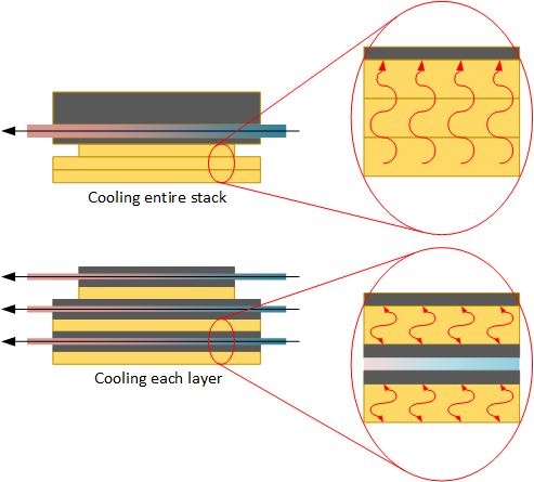
What happens when we start stacking dice one on top of another? Now the top surface of a lower die and the bottom surface of an upper die are blocked from any of the heat-conducting help a single die normally has. So heat from the bottom die goes into the top die – or tries – even as heat from the top die goes into the bottom die – or tries.
And that’s with just two stacked dice. What if we have a Dagwood sandwich of a stack? We’ve got several heat generators all sending gifts of heat to each other like so many families exchanging Christmas fruitcakes, with no clear way to dissipate it. And no, you can’t effectively regift heat the way you can fruitcakes. What to do??
I Need a Drink!
You can try to run water (or some liquid coolant – more on that in a minute) through channels created between the dice in the stack. It’s like all the cooling pipes embedded into Hoover Dam to help dissipate the heat of curing without damaging the structure. That seems to have worked for the Dam, but for chips? Well, it can sort of work, but we must account for the start of the flow, where the liquid enters the piping, and the end of the flow, where the liquid is collected, presumably to be sent to some kind of heat exchanger if it’s going to be recycled in a closed system.
But what happens while the liquid is flowing? It’s dutifully collecting heat, unburdening the dice it’s tasked with protecting, and taking that burden on itself. And, just like the therapist who has been hearing people’s crap all day and, by the end of the day, has no more capacity for hearing crap from the spouse, the liquid warms as it flows so that it can’t do much for the last circuits on the chip that it attempts to cool. You end up with a heat gradient across the chip in the direction of flow, and you may well end up with circuit hot spots in places that aren’t being effectively cooled. That simply won’t do.
In such a system, the liquid typically doesn’t touch the die directly; it rather flows through micro-pipes that place the liquid near, but not on, the die in heat-exchanger fashion. But that separating material isn’t always a good thermal conductor, limiting the effectiveness of the heat transfer.
So there’s another approach that’s been worked for a while called impingement cooling, about which Imec announced some interesting results. Basically, it means spraying liquid directly onto the backside of a die using an array of micro-nozzles. Because different parts of the die are being sprayed with fresh coolant – not coolant that’s already worn out from heat from some other place – the cooling can be more effective and uniform.
The coolant can vary; Imec used de-ionized water because it’s just so good at removing heat. Of course, if things get too hot, then it can vaporize, which usually isn’t a good thing in enclosed spaces. Other coolants can be used, but they typically involve a compromise on how quickly they can remove heat.
Since the liquid leaves the so-called plenum (apparently an HVAC term; if an automotive term were used, it would probably be called a manifold) and impinges directly on the wafer, there must be some way to collect it back up so it can be removed (and, presumably, recycled). So there’s a second plenum – and set of holes – that suck the coolant back up and transport it out.
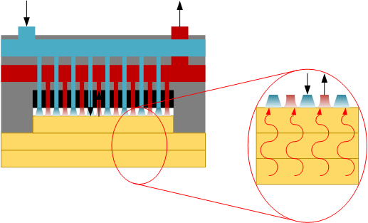
Now, you’ll notice that this cooling arrangement – unlike one option illustrated above – affects only the top die. There’s no inter-die cooling going on. So that means that the heat from the bottom die must travel all the way to the top to be removed.
I asked about this, and they confirmed what’s probably obvious from the drawing (even though it’s not to scale): the cooling infrastructure is just too thick to place between dice. For proper operation, it needs to be on the order of 100 μm thick, which is incompatible with stacked dice that need to communicate at high speeds.
So their ideal recommendation is for a three-layer stack: an I/O or common layer on the bottom; a memory layer in the middle; and a core layer on top. The idea is that the core layer generates the most heat, so it’s closest to the cooling.
In the event that you want to do something different, they say that there’s no real way to provide a generic estimate on how high a stack could go. It depends (obviously) on the power of each die. Less obvious is the thermal resistance of the die-to-die connections; how you mate the dice together affects how efficiently they can move heat upwards. So, with specific dice and technology in mind, you can do an estimate. Absent that, there’s no good answer.
Optimal Impingement
OK, so we’re cooling the top of the stack. But how best to do this? It’s not necessarily a new concept, but prior attempts have built the whole enclosure out of silicon, special ceramics, or metal – all expensive. What’s new is the ability to use micro-machined plastic for a much less expensive approach.
There are a couple of ways to do this, both of which place a limit on how small the nozzles can be. Injection molding is one option; 3D printing is another. Imec optimized the arrangement to work with dimensions that can be supported by these approaches; if smaller nozzles are needed, then one probably has to move to silicon fabrication techniques, and you’re back to higher cost.
The next question is how to optimize the material, the dimensions, and the construction. They found that the specific material had little effect on cooling. After all, there’s no material between the coolant and the die, so it’s not in the thermal path.
As to the nozzles and arrangement, they found that arrays with more, smaller nozzles worked best. Those arrays require higher coolant pressure, which affects the pump, but they also found that performance saturates, so there’s a practical limit to the pressure. Additionally, if you were designing a custom system for a die that had significant hot spots, you could presumably use more nozzles over that spot, increasing the heat transfer where it’s needed most.
I’ll leave the details to the papers below (which you may have to pay for, as I’m not at liberty to distribute them, nor do I have open-access links).
More info (both behind paywalls):
“3D Printed Liquid Jet Impingement Cooler: Demonstration, Opportunities and Challenges”


What do you think of both impingement cooling and Imec’s approach to it?
For one thing, bare metal programmers mob coding in cool showers just got that much more interesting. Impingement makes much of passivation that can keep sending the heat along, though it’s hard to imagine it keeping up with the IBM (well, GlobalFoundries now) microchannel version that has us imagining Power9 and Power11 systems full of the ALD version of sawblade thermal accomodation plus vias that go straight through the silicon. SRAM with cooling!?
_Joule_ publishes the orchid affacionado’s version, with nanofibers doing the conducting without much working fluid or regular spritzing to keep them perky. It’s still an open problem whether plumbing octanol through graphene sheet to the roof radiator or (if it’s cloudy) a local kitchen is a talent one can have as an alternate to the swagelok ‘convention.’ C’mon smart ovens, close the gap!