

Recently (by which I mean over the course of the past year or two), with respect to artificial intelligence (AI) at the edge (where the “internet rubber” meets the “real-world road”), I’ve been bemused and bewildered, flabbergasted and dumbfounded, and entranced and enthralled. To cut a long story short (which is opposite to the way I usually like to do things), I’ve been captivated by courageous claims and tempted by tortuous promises of delectation and delight.
As I pen these words, I’m thinking about things like affordable, off-the-shelf microcontroller units (MCUs) or related single-chip offerings with sufficient on-chip memory and processing power to be able to perform tasks like facial identification (“I see a human face”) and orientation (“it’s looking my way”). Mayhap even facial recognition (“that face belongs to Max the Magnificent (may his reign last for 1,000 years)”).
“What would you do with one of these little scamps?” I hear you cry. I’m glad you asked. I have a very specific task in mind. Based on this task, I’m issuing a challenge to any off-the-shelf MCU or AI-enabled chip manufacturer who cares to take up the gauntlet.
“But what is this challenge whereof you speak?” I imagine you whispering under your breath in fearful awe and dread anticipation. Worry not, because I shall expound, explicate, and elucidate in just a moment. But first pray let me set the scene.
A few years ago, it occurred to me that I was substantially closer to my 100th birthday than I was to my 1st. This may have been around the time that I was celebrating the 21st anniversary of the 21st anniversary of my 21st birthday… or not… I no longer recall. I don’t like to boast, but these days I’m better at forgetting things than I’ve ever been, and I don’t even think I’ve peaked yet.
So, I resolved to do what anyone else would do in a similar situation. That’s right. You’ve guessed it. I decided to build a Countdown Timer to display the Years (YY), Months (MM), Days (DD), Hours (HH), Minutes (MM), and Seconds (SS) remaining to my 100th birthday, which will take place at 11:45 a.m. British Summer Time (BST) on 29 May 2057.
This might be a good time to mark the date in your calendar (also make a note that I like chocolate).
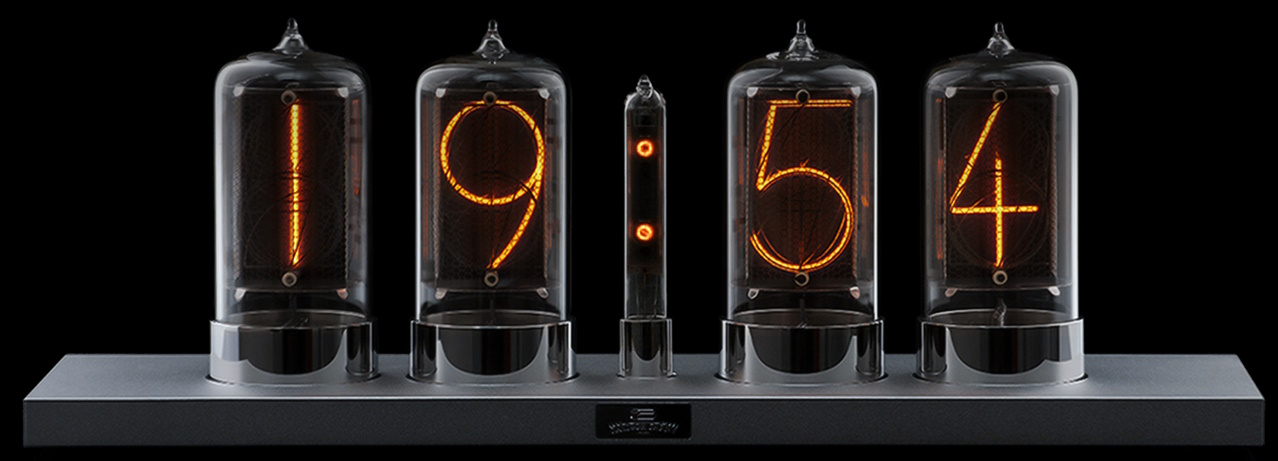
My first thought was to use Nixie tubes. My chum Dalibor Farny, who is based in the Czech Republic, handcrafts custom creations that bring tears of joy to one’s eyes. We are talking 2” wide by 4” tall tubes that take your breath away. This is especially true of the six steampunk-inspired tubes—with copper anodes and bronze bases—that are happily displaying the time here in my office (these comprise one of only two such steampunk sets Dalibor ever created).
An example of Dalibor’s awesome handcrafted Nixie tubes (Source: Dalibor Farny)
I think it’s safe to say that I love Nixie tubes as much as the next man or woman but… there are downsides, including the fact that they aren’t cheap, especially if you want to flaunt 12 digits on your display. Also, the fact that they require 170 volts can be a bit of a pain, both figuratively (design-wise) and literally (if you touch the wrong bit during the build).
As an alternative, my initial incarnation was based on Lixie displays. At 2” wide by 4” tall, these tricolor LED-based alternatives to classic Nixie tubes are spectacular in their own right. Each Lixie features 10 sheets of transparent acrylic. Each sheet of acrylic is etched with one of the digits 0 through 9, and each is edge-lit from the bottom using two WS2812B devices (a.k.a. NeoPixels).
Even better, the etched number font flaunted by the Lixies looks identical to that used in an equivalent-sized Nixie. I asked Connor Nishijima (the creator of the Lixies) about this. He told me that—as a starting point—he’d opened a broken Nixie tube and imaged its filaments using a regular document scanner.
I just rooted out an old YouTube video showing an early experiment in which I simply displayed a sequence of random numbers on my Countdown Timer.
On the one hand, this really was rather tasty. On the other hand, it must be acknowledged that this bodacious beauty was a tad on the large side. I’m almost embarrassed to say that it was 42” wide.
Why am I talking in the past tense? Well, sad to relate, my original Countdown Timer is no more. Much like the Norwegian Blue featured in Monty Python’s classic Dead Parrot sketch, it has expired and gone to meet its maker.
I have a little tear in my eye as I write this. A few months ago, I temporarily stored the Countdown Timer on top of some shelving in a closet at my home while I turned my attention to another project. Then, just a couple of weeks ago, I heard a resounding crash. I entered the closet to find the shelving had collapsed and my Countdown Timer was in pieces on the floor with all of its Lixies shattered to smithereens. “Oh Dear,” I said to myself (or words to that effect).
A few days ago, I was chatting with my friend Joe Farr, bemoaning the fate of my erstwhile Countdown Timer. Joe suggested I recreate it using IV-6 vacuum fluorescent displays (VFDs). These have lots of advantages, including their steampunk look and feel. Also, they are very affordable, costing only $2:50 each from the Tube Store. The combination of low cost and small size means I can afford to implement a 4-digit year, so my display will now look like:
YYYY MM DD HH MM SS
Also, these VFDs require only 40V (as opposed to the 170V required by Nixie tubes), which makes everyone’s lives easier. Joe is going to build one of these timers himself. We are going to add a tricolor NeoPixel under each VFD to support special effects. We decided to use a 12V supply, which we will boost up to 40V for the VFDs and drop down to 5V for the NeoPixels, with a further drop to 1.5V for the VFD filaments.
Since we are going to publish this project so other people can create one if they wish, we decided to mount each digit on its own small circuit board. In addition to the VFD, this board will carry an 8-bit shift register and a VFD driver integrated circuit (IC). This means users will be able to implement as many digits as they wish by simply daisy-chaining these boards together, with the whole chain requiring just six digital outputs from whatever MCU they decide to use as a controller (5 bits will be used to control the shift register chain, and 1 bit will control the NeoPixel string).
There are, of course, a lot of nitty-gritty details, like the fact we are going to have “spacer boards” that separate the groups of digits with slashes or colon characters, so the display will really look like the following:
YYYY/MM/DD HH:MM:SS
It was at this point we ran into a problem. Well, more of a “gotcha,” really. Joe and I had both placed our IV-6 VFD orders from suppliers in our respective countries (Joe in the UK, me in the USA). Except for the NeoPixels, we decided to use LTH components because those are easier for hobbyists to work with. Joe whipped up a quick first-pass design of our printed circuit board (PCB) as shown below.
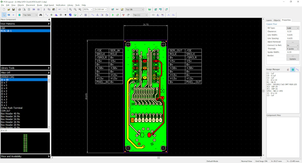
First-pass design for single VFD board (Source: Joe Farr)
Hmmm. This board ends up 32mm wide. The problem is that the IV-6 VFD tubes are only 13mm in diameter. I created a quick representation using Microsoft Visio. The spacing is all wrong. Bummer.
The solution we opted for was to move to IV-11 VFDs. In addition to being a bit taller, these tubes are 22mm in diameter. With our 32mm boards, this means we’ll have a 10mm gap between tubes. Another Visio mock-up indicates that this will look PDG (pretty darned good). The only real downside is the cost, which is $8 a tube, but that’s still not too bad.
Furthermore, Joe suggested that, since we already have the smaller IV-6 tubes on order, we could spin a couple of sets of smaller boards using surface-mount components just for our own use. I joked that this could be my “Travelling Countdown Timer.” Joe replied that, since everything is powered from 12V, I could use the smaller model in my car as a “Dashboard Countdown Timer.” Hilarity ensued.
There is, however, a fly in the soup and an elephant in the room (as I’ve mentioned before, I never metaphor I didn’t like). Can you guess the problem?
Here’s the deal in a crunchy nutshell. If we assume 33 years to the Countdown Timer reaching 0000/00/00 00:00:00, then this is 33 x 365 x 24 = ~290,000 hours. The problem is that a typical VFD expectancy is only around 10 years (~90,000 hours). This means I’ll never know when the countdown is complete. We’ll all be sitting there in our party hats not knowing when to start blowing our party horns (frowny face).
The Challenge
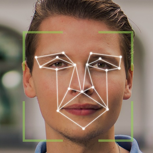
So, this is where we come to the challenge mentioned at the beginning of this column. What I want is to be able to take the output from something like a webcam with 1080p resolution and feed it into a small breakout board (BOB) carrying an off-the-shelf AI-enabled MCU or similar.
I want this device to be able to detect when there are people in the room. More importantly, I want it to be able to detect when one or more of these people are looking in the general direction of the camera, which will be mounted in proximity to the Countdown Timer.
Whenever anyone is looking, I want this device to set one of its GPIO pins high, otherwise I want the pin to be low. I can feed this signal to the MCU in my Countdown Timer, which will use it to enable or disable the displays. This way, my VFDs will easily stay the course and be resplendent when their time comes to shine on that frabjous day.
Bonus points will be awarded if this little rascal can be trained to recognize my own visage—even better if it could also count how many fingers I was holding up—but these are “cream on the cake” details.
The more I think about it, the more I realize I could use this capability on myriad projects. I bet others could use this too. So… are there any manufacturers of affordable, standalone, AI-enabled MCUs (or similar) out there who are up to this challenge? And, while we wait, do you have any thoughts you would care to share on any of this?


Hi Max,
I think we here at Alif semiconductor can help you with this! I have an application that detects faces running on our tiny Vision AppKit, if you think that would work I’d be happy to send you one 🙂
Demo here – https://www.youtube.com/watch?v=BXnVC1GSQls
If you need some additional background on our Ensemble family of AI-enabled MCUs, we did a we did a Chalk Talk together with Amelia a little while ago. Check it out!
https://www.eejournal.com/chalk_talks/the-future-of-intelligent-devices-is-here-alif-semiconductor/
Hi Henrik — your Vision AppKit is perfect — just what I’m looking for — I wrote about your Ensemble AI-MCU family a few weeks ago https://www.eejournal.com/article/new-mcus-provide-102-the-performance-at-10-2-the-power/ The combination of your chip and the miniature camera on that tiny Vision AppKit board will be perfect — I can’t wait to see it (no pun intended 🙂
Hey Max! New reader here. So cool that you build project in your articles, brings engagement while reading to a new level. Hope to get a progress update with the Vision AppKit!
Hi there — thanks for your comment — I don’t do this with all my projects — but sometimes they are relevant to some new technology. My friend Joe is re-spinning the PCBs — my VFD tubes have arrived — Alif are working on tweaking their Vision AppKit to give me the signal I’m looking for — I will indeed post more about this in the future. Happy Wednesday 🙂