


Do you know where you are?
OK, dumb question; of course you do. You have a smartphone with GPS that tells you (and probably way more people than you might be comfortable with) where you are. But, if you turn GPS off or were inside a building that blocked the GPS signal, then would you know?
We’re talking about location services here, and there are two essential questions, each with a different answer:
- Given an “asset,” can I track where it is within a moderate range – like within a store?
- If I am that asset (I know I’m good at being at least the first syllable), can I figure out where I am?
The difference boils down to this: given some location service, the first scenario has that service figuring out where an asset is. The second scenario has that service helping the asset to figure out where it is. There are two new Bluetooth capabilities that make this possible: angle of arrival (AoA) and angle of departure (AoD). We’re going to sort through those today.
I came to all of this through a conversation with Silicon Labs. They announced both WiFi and Bluetooth improvements in their software that runs on their Gecko family. And the big news on the Bluetooth side is this new location-finding capability.
So let’s work through these two functions to see how they work. And I’ll confess… I’m not an RF specialist, so some of this wasn’t obvious to me without some studying. Hopefully that will help for any of you that are also not RF specialists.
Incoming!
Let’s start with AoA, which lets us track an asset. In order for this (and, frankly, AoD) to work, Bluetooth has added something to their transmission packet: a continuous-tone extension, or CTE. This is a “pure” tone sent at the carrier frequency plus 250 kHz. Note that some documents out there talk about sending this tone at “the carrier frequency of 250 kHz,” which confused me, since I thought BT operated in the GHz range. Indeed it does; such references turn out to be in error.
By the way, this CTE is the equivalent of sending all “1”s for the requisite period of time. It’s not “whitened,” and it doesn’t affect the CRC. It lasts for 16-160 μs. The idea here is to provide a pure tone for long enough that the receiver can gather IQ* data without worrying about modulation messing up the measurements.
Importantly, you can figure out the angle of the signal (more on that in a sec), but not the distance away. Yeah, you could read the power, but you don’t know enough about the sending power, so that doesn’t help. We’ll need to do more work to get a specific location, but for now, let’s start with the angle.
The system setup is as follows: a number of locators – similar to beacons – are placed strategically around an area. The locators feed a gateway, which may feed a position engine (more on the latter two in a minute).

(Image adapted; original credit Silicon Labs)
Each locator has an antenna array, and that array allows the locator to estimate the angle from which the signal is arriving. The practical details of that are pretty complicated, from what I can tell, but the basic idea is simple. It’s just that real-world noise and multipath signals make it harder than it would be in an ideal world.
In the figure below, you see the signal arriving at both antennas. It’s assumed that the signal is far away, so the lines are parallel (or close enough to be considered parallel). The signal arrives at the right-hand antenna slightly before the left-hand one, and, by knowing the distance between the antennas, you can figure out that phase shift. Knowing that, basic trig gives you the angle of arrival.
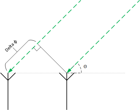
Real-world arrays will have more antennas, and their arrangements may vary. From a circuit standpoint, this is multiple antennas using a single receiver with a switch that sequentially measures the signal on each one. The length of the CTE portion of the packet makes possible this set of measurements.
The angle calculation can be done within a locator, although there are some options here. The locator can do the angle calculation, or it can pass the IQ data to a gateway, which can, in turn, do the calculation. But we’re still not in a position to get location because all we have is the angle. We don’t have a distance. For that we need triangulation (or trilateration). And that takes multiple locators.
So that gateway will calculate angles if it has to, or, if not, it can calculate the actual location – or it can pass the angle info from the different locators off to a position engine to do the work.
Why might you not calculate the angle in the locator? Apparently, this places a high load on the locator, reducing the receive duty cycle and taking, on one estimate, 200 ms for the calculation. (yeah, I know, that will vary by processor and language and… and… this provides a ballpark.)
Service!
OK, so let’s turn this around now and look at AoD, which helps us locate ourselves. Instead of the angle of arrival to the receiver, it will be the angle of departure from some transmitter. The signal is sent by a beacon, which will need its own antenna array (with single transmitter and switch).
The receiver – that is, the mobile device – has a single antenna that receives all of the signals from the different antennas on the beacon. But there’s a critical difference: for AoA, the receiver contains the array, and so it knows the array geometry and can manage the calculations with no help from the asset transmitting the signal. But with AoD, the mobile device is the receiver, and it doesn’t have the array. How does it know the distance d between the antennas? That’s needed to calculate the angle. It also helps to know the timing of the antenna switching so that you can sample at the right time. (That timing doesn’t figure directly into the equation for the angle, which is why I say that it “helps.”)
I asked Silicon Labs about this, and they pointed out that the spec handles these details. Upon further inspection, there are two key details in the spec:
- The value of d in the prior figure is a profile parameter, and it’s exchanged between the beacon and the receiver.
- The timing of the switching, referred to as sample slots, can be either 1 or 2 μs. I looked for a while through the (2985-page) spec and couldn’t find exactly how the transmitter tells the receiver which choice it has made, so I’m going to assume it’s also a profile thing.

(Image adapted; original credit Silicon Labs)
You’re going to need 3+ beacons to get accuracy. Done well, both AoA and AoD can get you down within around a half meter of the true location. And, unlike AoA, the burden on the beacon for AoD is apparently light.
So… turn off your GPS. Now… do you know where you are?
*Yeah, I had to look up IQ also. It’s amplitude/phase info of the signal, but rather than being expressed in polar coordinates, it’s converted to Cartesian. Or you can find a more complicated explanation on Wikipedia.
More info:
Silicon Labs Bluetooth Direction Finding
Bluetooth 5.1 Feature Overview


What do you think of the new Bluetooth location capabilities supported in Silicon Labs’ latest release?