


Let’s start by getting one thing straight: Minima Processor is not a processor company. It’s a processor-related IP company, and, most specifically (at least for now), it’s a DVFS (dynamic voltage and frequency scaling) IP company.
If you’re not familiar with DVFS, it’s a way of changing power supply rail voltages and clock frequencies on the fly so that you can push hard when necessary and possible and then throttle back at other times. The idea is based on the recognition that it’s simply not realistic to set a single voltage and frequency – so-called static margining – for all occasions and hope to yield enough good dice. Too many variables conspire in finding ways for the processor not to work. And yes, this could, in theory, be used for anything, but mostly (perhaps exclusively) it’s used for processors.
Working Near Threshold
Minima has a goal of cutting the power that might result from an LP (low-power) process by 90-99%. One way they’re doing this is by going with near-threshold design – that is, lowering the power levels so that they’re just above the transistor threshold voltage.
This is distinct from sub-threshold design, which we’ve also seen before. Both Ambiq and PsiKick dare to do this, but they have an extra burden: they have to redesign all of the standard libraries so that they’ll work below threshold. Not easy; lots of work.
By contrast, Minima can reuse the existing libraries. It’s just that those libraries haven’t been well characterized near the threshold. So Minima has had to do that. But that’s not a design project; it’s a simulation or measurement project. It’s much easier than designing new library circuits.
But the whole issue of margin – making sure you’ve designed everything so that it has room to work in all situations on all good dice from any lot – gets messier near threshold. Variations tend to spread much wider, making static margining that much trickier than it already is, as you can see in the graph below. Minima estimates 50% yields using a static approach – not an appealing business model.
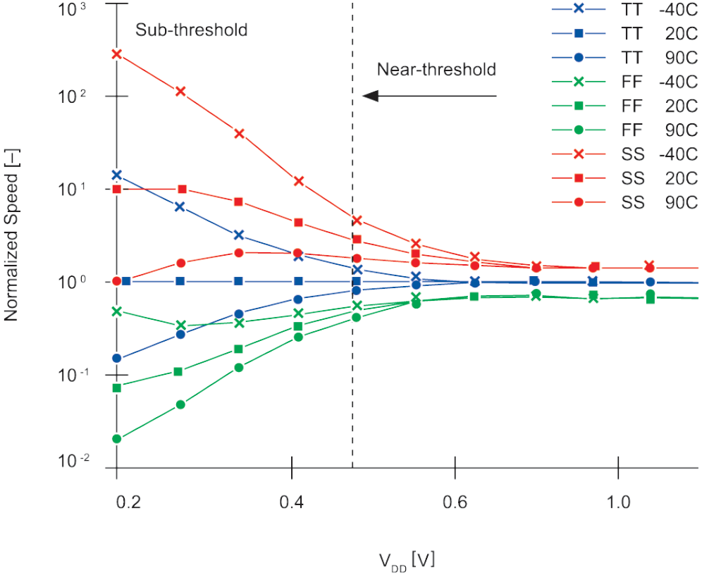
(Image courtesy Minima)
Going Without the Tables
We looked last year at how Sonics was adding DVFS to its power-management suite. But Sonics uses the traditional approach to DVFS: tables that specify which frequency to use for each voltage (or vice versa). In a table-based setup, you can use only the values that are explicitly in the table; there’s no interpolation (or extrapolation). And it is usually controlled by the application issuing commands to the system via a DVFS interface.
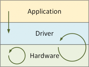
Minima says that they’ve taken this notion one step further, automating much of it at a very low level. In fact, they have three levels at which their system works, using a mixture of hardware, driver-level software, and control from an application via the DVFS interface.
We’ll start from the bottom, since that’s where the most action might be. This whole thing is driven by a number of monitors placed on strategic paths. Exactly how that’s done is, at least at present, secret sauce. So let’s stipulate that it works.
They point out that they monitor the actual circuits, not proxies for the circuits. They’re concerned that any proxy might differ from the real thing, and, if there were a risk that some task might not finish during a clock cycle, then missing that fact would not be good.
If the monitors suggest that the current cycle might not last long enough for everything to get done, they can delay the next clock edge to make sure there’s enough time. Think of it as letting a gear or sprocket slip a tooth or two. Of course, this isn’t a frequency change; it’s a phase change. But it happens automatically at the hardware level.
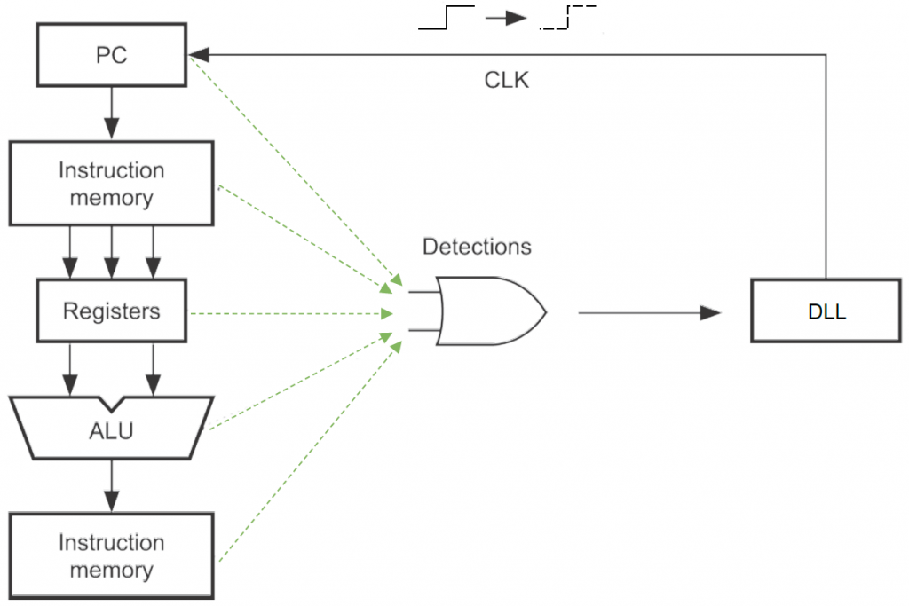
(Image courtesy Minima)
The driver also watches what’s happening with the detectors in case the voltage needs to be raised. This instigates an iterative process where the driver and detectors together establish a new frequency and voltage. The values don’t come from a table, so the process can converge to any values.
To be clear, the reason why such voltage changes might be needed come from changes in operating conditions. Temperature is a good example; things might be working fine, but then, as the chip heats up, it gets bogged down, and so it needs a new operating point.
Minima says that some cycles will be used up in this iterative process, but that it’s quite rare in the grand scheme of things. So there’s no measurable impact on latency.
Finally, the application can request a new operating point. To the application, this looks like standard DVFS, so the nuances of what’s happening under the hood won’t matter. Note in particular that the app doesn’t ask the hardware; it asks the driver, and the driver can then do its usual converging as necessary.
We’re mostly talking about small, low-level, single-core processors here. So the driver is going to be running on the same processor whose operating point is being changed. With some additional engineering work, this could also work on a multicore processor, with the driver running on a processor different from the one being adjusted.
Diving Deeper
But this left me with a question: if setting the power is iterative, and, if you have the driver running on the same processor that is having its operating point adjusted, then, if the iterative process takes things out of operational range, then the driver can no longer work, and it falls apart. Clearly that can’t be the case, so with some thought and clarifications from Minima, I was able to conjure up the following detail on how this works.
The biggest thing to keep in mind is that this isn’t a black-and-white, works-or-doesn’t-work thing. Remember that there are these monitors or detectors throughout the hardware. If they report an issue, then you get the clock push-out to ensure that the task is completed in that cycle. So there’s a robustness here that can tolerate a certain level of voltage being too low or frequency being too fast.
This, then, gives us a gray area between where everything is running smoothly on the one side (although possibly with more power than is really needed) and where nothing can work on the other side. Within that gray area, the way you tell how close you are to the top or bottom is through the frequency of these detector events. That’s what the driver keeps track of. If there are only a few such events, then you can trundle along with the current operating point, making the occasional clock-edge adjustment.
But if the number of events rises above some threshold, then the driver will instruct the hardware to raise the voltage. If that new voltage still has too many events occurring, it will repeat and raise the voltage again. This is the iterative thing.
If the application itself requests a change, this could be implemented as an interrupt. So the application would pause while the iterative voltage-change thing happens. Once the new operating point stabilizes, then the app can resume when the interrupt handler terminates. Here again, Minima expects any latency impact to be minimal.
But it’s worth diving deeper into this scenario as well. What is the nature of the DVFS interface? Typical DVFS is implemented through tables, so you might imagine that an application could query as to what values are available in the table and then select one. You might also think this is too much detail for an app to have to work with. And you’d be right. But, more to the point, Minima doesn’t have tables, so this would completely break down with them.
Turns out, however, that they interact with the driver based on three possible profiles: high voltage and fast clock; medium voltage and medium clock; and low voltage with a slow clock. These profile points are guaranteed to be safe, so there’s no risk of accidentally pushing the processor out of the range where it can work. It may land in the gray zone (probably will), and then the clock push-outs will keep it running while the driver iterates on the power level if the frequency of clock push-outs is too high.
Setting vs. Selecting a Voltage
But this raises yet one more question at the low hardware level. For typical table-based systems, you have a number of rails or clocks that are preset according to the values in the table. Making a change means changing from one rail to another.
But Minima isn’t table-based, so there are no specific rails to connect to. And the voltage can be set to arbitrary values, so multiple rails wouldn’t even make sense. That means changing the actual value on a rail, and it would seem to me that such a change would take a while to stabilize.
Minima says, however, that they have included their own programmable DC/DC converter in the IP. And it responds very quickly: establishing a new voltage takes no longer than a memory write. This means you can iterate in the nanosecond domain without suddenly having to jump to the microsecond domain (or worse) for voltages to stabilize.
Making It Happen
We’ve looked at how this works, but how would you actually integrate this IP into your design? At this point, you’d look to Minima for help. This isn’t simply IP that you bolt onto the side of your circuit; it’s intrusive in the sense that the detectors have to be inserted into the processor design. That has to happen at the netlist level, when circuit details and delays are well known.
In general, the process is:
- Identify all critical paths
- Eliminate false paths
- From the remaining critical paths, identify the ones to be monitored.
Their eventual goal is to automate this process.
In practical fact, once they do this the first time for a given processor, then that processor is available to others. So it’s not like this has to happen independently for each and every design. That would be a bad business model, since every design would require collaboration with Minima, and engineers (given that they’re human – at least until our robot overlords decide otherwise), don’t scale so well.
So, if you’re doing the first design on some processor, then you get with Minima and they deliver back to you a modified processor that has all of the bits and bobs integrated. You then use that processor in your design instead of the original one. Minima, meanwhile, makes the modified processor available to others.
More info:
Minima Processor


What do you think of Minima’s approach to DVFS?