

“I believe the future is only the past again, entered through another gate.” – Arthur Wing Pinero
We know what a task state segment (TSS) is, but where does it live? The short answer is, anywhere you want it to. Like any other memory segment in the x86 world, you can place the TSS just about anywhere in physical RAM as long as you create a segment descriptor that tells the processor where to find it.
The segment descriptor for a TSS looks just like a segment descriptor for a normal code, data, or stack segment. In fact, you’d have to be an x86 processor yourself to tell the difference. As the figure shows, it’s a 64-bit structure that defines the base address of the segment, its length, and a smorgasbord of status and control bits that determine how it’s used.
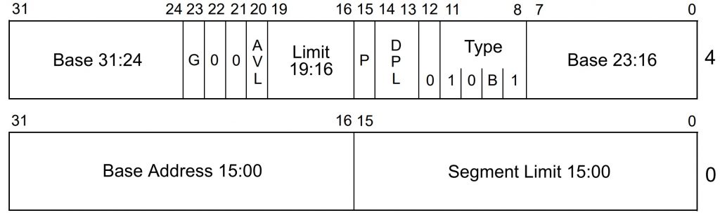
The magic bit field in a TSS descriptor is in the upper half, at offsets 8–12 (decimal). You’ll want to make this 01001 (binary) to distinguish it from a code segment (11010) or a data segment (10010), or all the other types of segments. The “B” bit (busy bit) at offset 9 tells the processor that this task is busy, meaning it’s either running now or was running before switching to another task. It’s set and cleared automatically by the hardware, so you shouldn’t mess with it. The processor will refuse to task-switch to an already-busy task, and this bit in the TSS descriptor is how it knows.
Since the base address field in the TSS descriptor is 32 bits long (albeit broken up into three awkward parts), you can put your TSS just about anywhere within the 4GB address space. And, since the limit (length) field is 16 bits, your TSS can be a lot bigger than the 104-byte minimum. Last week we saw how that extra space can be put to use tweaking I/O address permissions. You can also extend the TSS with extra user-defined data in case there’s anything you want to store that’s not already included in the TSS.
You have to put all your TSS descriptors in the Global Descriptor Table (GDT), not in the LDT or the IDT. That’s because task segments must be accessible to the processor at all times and not be task specific. It wouldn’t make sense to put one task’s state information in a place that’s accessible only from a different task. TSS stuff needs to be global.
Making the JMP
Okay, let’s say we’ve created two task state segments, one for each task we want to run. And we’ve created two TSS descriptors, one for each TSS. Let’s also assume we’re using really simple software task switching, where each task voluntarily jumps to the other task, which then jumps back to the first one, in an endless ping-pong loop.
How, exactly, does one task jump to another? It’s almost too easy. You just JMP to or CALL the other task as if it were another section of code. Since the beginning of time, x86 processors have had “near” JMP and CALL instructions and “far” JMP and CALL instructions. The near kind means you’re changing the flow of control to code within the same code segment. (In the really early days, that meant code within 64KB of your current position.) A far JMP/CALL means you’re leaping to code in a different code segment. Task switching just extends that concept.
In any far JMP/CALL, you have to specify both the code segment and the offset that you want to jump to. (That makes far JMP/CALL instructions longer than near JMP/CALL instructions, which need only the offset, in case you’re counting bits.) Well, the same rule applies here, except the “code segment” you specify is really a TSS descriptor.
There’s no special “switch tasks” instruction in the x86. You use the same old JMP or CALL instruction as always. It just behaves differently when the hardware realizes that the segment descriptor you’ve specified is really a task segment descriptor and not a code segment descriptor.
The Task Gate
There’s another way to switch tasks that adds a level of security while also reusing the familiar JMP and CALL instructions. It involves something called a “task gate,” which is yet another new type of segment descriptor that you get to create and load into the GDT.
A task gate looks a lot like the other types of segment descriptors except that it’s mostly empty space. It’s 64 bits long, but only 16 bits are really significant, plus a handful of configuration bits that tell the processor it’s a task gate.
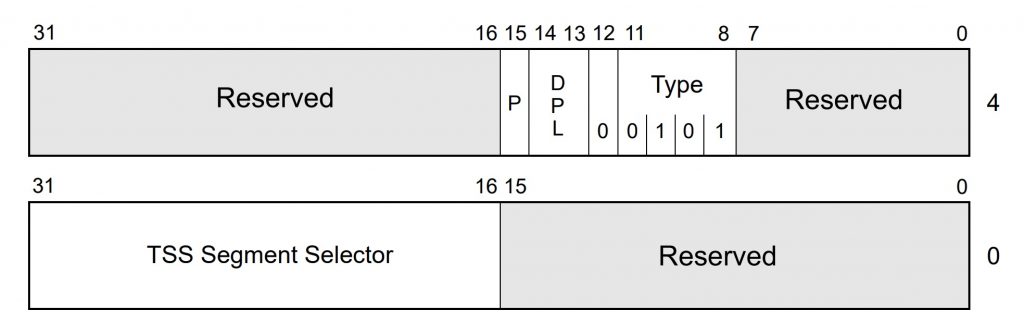
The 16-bit field from offsets 16–31 (decimal) points to a TSS descriptor, like the one we saw above. It’s not an address, it’s a selector, an index pointer into the Global Descriptor Table. As before, you can use a far JMP or a far CALL instruction to force a task switch, but instead of specifying a destination code segment, or even a task segment, you specify the task gate. The task gate points to the task segment descriptor, which points to the task state segment (TSS) itself, which loads all the other registers. How’s that for indirection?
The net effect is the same either way. You can JMP or CALL to a TSS descriptor or to a call gate. The instructions are even encoded the same way. The only difference is the object they reference, not the instruction itself. The CPU figures this all out on the fly, in hardware.
Rank Hath Its Privileges
So… what’s the point of a call gate? Privileges. The indirect route gives you another option for managing privileges and controlling which sections of code are allowed to call which other sections of code. All modern x86 processors implement a four-level privilege hierarchy, which takes the form of a two-bit field attached to each and every segment of code. As a rule, lesser-privileged code is not allowed to JMP or CALL to code with a higher privilege level. But there are exceptions.
Juggling these rules and exceptions is part of your job as programmer, and a lot of real-world x86 programs just don’t. They ignore the built-in privilege hierarchy and substitute their own security system (ahem, Microsoft) or just dispense with privilege checking entirely. That’s fine and dandy, but you can’t make the processor’s privilege-checking hardware go away. It’s always active and, if you set it up properly, pretty darned useful.
We’ll leave the detailed privilege discussions for later, but for now, a task gate provides a slightly different way to switch between tasks with slightly different privilege rules. Bits 13 and 14 in the task gate above define the DPL, the descriptor privilege level. This matches up very nicely with bits 13–14 of the TSS descriptor, which also parallels the DPL assigned to every code segment. So, we have at least three different sets of privilege bits in play here. It’s the interaction between them that makes secure programming so much fun.
Task gates also manage access in another way. Recall that TSS descriptors are global; they have to reside in the GDT. But task gates can be local. They can be stored in an LDT (Local Descriptor Table), which means that only a task with the task gate in its LDT can “see” the task gate and, therefore, switch to that task. This allows you to restrict access to the gate (and its associated task) by selectively dropping it into the LDTs of only those task(s) you want to use it. Sneaky.
Next up: the perils and pitfalls of setting up your first tasks and launching a task switcher.


