

“What fresh hell is this?” – Dorothy Parker
Want a fun late-summer project? Looking for a source of frustration? Need a quick hack to polish up your programming resume? Let’s create our own RTOS using the built-in hardware features of the x86 processor family and very little code.
Calling this an “RTOS” might be overselling it a bit. A real, real-time operating system will have lots of advanced features that this won’t have. This is more of a scheduler or task switcher than a fully formed operating system. Still, it’s both useful and educational. If nothing else, it highlights some of the wondrous features lurking inside every x86 processor. Features that, alas, have been unappreciated and underutilized.
This week we’ll start off with the basic structure and theory of operation. Code samples and usage tips will come later.
Task State Segments
Hidden inside every x86 processor since the days of the ’386 is an elaborate task-management system. All by itself, the chip does its best impression of a small real-time kernel, replacing tons of software. It’s so useful and powerful that you can piece together a rudimentary RTOS with just a dozen lines of assembly code. How’s that for free software?
The first key component to all of this is something called the Task State Segment, or TSS. In any multitasking environment you need a place to store the complete state of each task – its registers, variables, pointers, status flags, etc. In a normal software RTOS, you do this by pushing everything onto the stack or (more likely) by writing it all into a special chunk of memory somewhere dedicated to saving each task’s state. When it’s time to reawaken the sleeping task, you restore its state from this special storage place.
The good news is, x86 processors can do this for you, storing all the relevant machine state into a 104-byte structure called a TSS, as shown below. You create one TSS for each task you plan to have, and each TSS lives somewhere in memory. After a little bit of initial setup on your part, the x86 processor will automatically handle storing and reloading each TSS every time a task is switched in or out. But that’s just the start. It gets better.
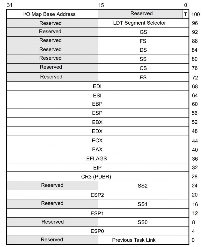
If you’re familiar with the x86 programmer’s model and register set, you’ll recognize most of the contents of the TSS. It has all the general-purpose registers like EAX and ECX, along with the segment registers (CS, DS, SS, etc.) as well as four stack pointers (one for each privilege level) – plus a few unfamiliar items. We’ll get to these in a bit.
But first, what exactly is a task? In the RTOS world, a “task” can be anything you want it to be, and in x86 land that’s still mostly true. You can have just a few tasks or many hundreds. Tasks can be related to each other or wholly unrelated. They can communicate amongst themselves or be isolated. It’s your call.
The major differentiator is that the x86 processor will try hard to keep tasks separated and independent of one another. By default, they’re isolated and don’t communicate or affect each other in any way. You can override this behavior and let tasks talk to each other and share data if you want, but it takes some work.
Tasks can optionally call other tasks, which means you can nest them or chain them together like subroutine calls. But tasks can also be “flat” and not nested, each one separate and autonomous, with no knowledge or awareness of its siblings. Different tasks can have different privilege levels (one of four), so some tasks might have more rights and responsibilities than others. For technical reasons, tasks cannot be reentrant or recursive.
Oh, and the task-switching hardware works in 32-bit “protected mode” on x86 processors, but not in 64-bit mode. Sadly, Windows and other major operating systems never leveraged the built-in task management, preferring their own software implementations, so later chips dropped support for it. More’s the pity. It’s still fully functional on all the latest x86 processors, just not in 64-bit mode.
Task Switching
You get to decide how and why tasks switch. You can do it in software, by having one task JMP or CALL another task. In those cases, the x86 will “sleep” the outgoing task by storing its processor state into its TSS and “awaken” the incoming task by loading its TSS into the processor. The whole process takes just a few dozen clock cycles, depending on the speed of your memory. Neither task knows that anything has happened. Unlike a subroutine call, no information is passed between the two tasks. The incoming task starts running from wherever it left off, with no awareness of time passing.
There’s no requirement to ever come back to the outgoing task. Again, tasks can be nested or chained together, but they don’t have to be. You might have a dozen tasks that all get an equal time-slice and run in rotation, or you might create a chain of single-shot tasks that never repeats, or you can dispatch tasks in random order. It’s all up to you.
If you use a CALL instruction to swap tasks, the incoming task becomes a “child” of the outgoing task. A subsequent IRET instruction (interrupt return) will switch back to the outgoing parent task, which picks up exactly where it left off. A child task can CALL another child task, and so on. The processor automatically maintains a linked list so it will know how to unwind the call chain. The only restriction is that you can’t CALL a task that’s already on the list. That is, tasks aren’t reentrant. You can only CALL a task once before it has to be “un-called” and made unbusy by unwinding the call chain.
If you use a JMP instead of a CALL, the incoming task does not become a child of the outgoing task and the two are not linked. There’s no expectation of returning to the outgoing task, although you can.
Where is this mysterious linked list? Ah, that’s one of the many things stored in the TSS. At the very bottom of the TSS (offset 0 in decimal notation), is a 16-bit field called Previous Task Link. This is managed by the hardware, not you, and it allows the chip to keep track of nested tasks. Every time you perform an IRET from a nested task, the processor examines this field to see which task to return to. Again, everything’s done automatically with no need for us to maintain it.
You can also switch tasks with a hardware interrupt, such as a timer. Instead of a JMP or CALL instruction that you deliberately place in your software, you might trigger a task switch asynchronously, with no cooperation from either the incoming or the outgoing tasks. In fact, this is a pretty common way to do task switching, with a timer ticking off regular task switches every few milliseconds. Any other hardware interrupt (an external switch, a signal driven by another component, etc.) can also be used to cause a task switch. In any case, the interrupt service routine (ISR) simply forces the JMP to cause a task switch.
In fact, if you do things right, the ISR itself can be its own task and the hardware interrupt will cause an automatic task switch with no software whatsoever. That’s a little more advanced (but pretty cool), so we’ll cover that in a later installment.
Finally, you can even have processor faults and exceptions trigger a task switch. The x86 architecture defines lots of faults (stack faults, protection faults, page faults, etc.), and each of these can be set up to cause an automatic task switch to a new fault-handler task. This has the advantage of separating the fault-handler code from whatever was running before it, plus it automatically saves and protects the state of the machine just before the fault. Simply examine the TSS of the outgoing task for clues to what happened.
TSS Options
Over at offset 96 (decimal) in the TSS we see another 16-bit field called LDT Segment Selector. This is a pointer to the task’s own private table of memory spaces. Modern x86 processors abolished the weirdly awkward segment:offset style of memory addressing long ago – except they didn’t, really. Those two-part addresses are still around, but now they use descriptor tables to define the boundaries of code, data, and stack segments. There’s exactly one global descriptor table (the GDT), plus as many local descriptor tables as you’d like. Each task gets its own local descriptor table (LDT), which means it gets its own memory space independent of every other task’s memory space. The LDT is optional, but if your task gets one, this is where you point to the base of it.
A few bytes farther along at offset 102 (decimal) we get the I/O Map Base Address. This is also optional, and it allows you to fine-tune the I/O addresses (as opposed to memory addresses) that your task can access. If you choose to use it, your TSS can grow in size by quite a bit.
Recall that x86 processors make a distinction between memory accesses and I/O accesses. They’re two separate address maps, one being several gigabytes in size and one just 64KB. Memory accesses use instructions like MOV, while I/O uses instructions like IN and OUT.
Memory segment descriptors and privilege levels define whether your code is allowed to access certain areas of memory. But I/O is much simpler: it’s either all allowed or all off-limits. The I/O Map in the TSS allows you to fine-tune that. Instead of a binary allowed/disallowed decision for the whole I/O space, the I/O Map gives you one bit for each of the 64KB different I/O addresses. If the bit is zero, your task is allowed to perform I/O operations at that address. If the bit is one, the task is blocked from I/O at that address.
At one bit per I/O address, a fully realized I/O map takes up 8KB of RAM, which is quite a bit larger than the normal size (104 bytes) of the TSS. Fortunately, you can leave off the I/O Map entirely, in which case the x86 defaults to its normal I/O mode for this task. You can also truncate the I/O Map after any arbitrary number of bytes. This saves space in the TSS, but only if the I/O addresses you want to enable are at the low end of the address map. If the address you want to enable is at 0x1FFF, you’re out of luck.
Here’s a trick: nothing says the I/O Map has to start exactly at offset 102 in the TSS. The 16-bit field there is a pointer to the start of the I/O permission table, not the start of the table itself. That means you can put the full table almost anywhere within 64KB of the TSS, and not necessarily contiguous with it. It even allows you to share one table among multiple tasks by putting different pointers into their TSS. Nice!
Okay, that’s the basics done. Next, we’ll look at different ways to JMP or CALL to a different task, how to handle privilege levels, and what the heck is a task gate?


This reminds me of my first Assembler code, back in 1976, 🙂
But any RTOS is only a common OS, with a time constraint, see Wiki
https://en.wikipedia.org/wiki/Real-time_operating_system
What about a real RTOS, as an example an OS written exclusively in VHDL/Verilog,
while connecting it to a body framework with sensors, actors and internal organs,
forming alltogether an embedded system and reacting in real-time to the world?
If then, we write some applications, which will be connected with each other,
and give a “little help” or jump-start in order to develop itself new apps,
via a self-learning mechanism(=self-programming app), this would be RT apps.
Furthermore, we could give the little fellow some computer space,
means capacity for both memory and processing, which would be
accessible step by step, according to its necessities all along.
This way, the RTOS will “allocate” dynamically and interactively
the space in order to create the required apps via self-programming,
enabling hereby the accumulation, storage and retrieval of knowledge.
Then we have a living machine, reacting in real-time same as a biological organism.
If you think this is only a dream or wishful thinking, well, this is really happening,
But hey, who wants to live forever, in a machine? Well, somebody will go for it.
Is it possible to run RTOS on a x86 architecture? As far I have understood RTOS is for low end microcontrollers where as general purpose os is for high end architectures. RTOS are developed to bring some OS concepts to microcontrollers. See the link below.
https://engineersasylum.com/t/how-to-get-started-with-rtos/258
Correct me if I am wrong. How is it possible to develop a RTOS on the top already running OS?
Expecting a replay.
Thank you.
Sure. You can run a real-time operating system (RTOS) on any type of processor, large or small. The RTOS does not run *in addition to* another operating system, like Windows or Linux or MacOS. It runs *instead of* those other operating systems. If you want your x86 computer to run Windows apps, you run the Windows operating system. But if you want your x86 computer to run real-time apps (which you will probably write yourself), then avoid Windows and run an RTOS instead.