


“Time’s fun when you’re having flies.” – Kermit the Frog
Mention “segmentation” to a marketing guy, and you’ll get a long discourse on demographics, targeted advertising, pricing brackets, and other arcana. Use the same word around an x86 programmer, however, and you’ll get a different response. He’ll either spit on the ground, roll his eyes, or punch you in the mouth. Your choice.
Memory segmentation is one of those defining features of Intel’s x86 processor architecture that users either hate or hate. Well, maybe not everyone. Sometimes segmentation can be used for good. But it’s an oddball feature that has morphed substantially over the years, and it may teach us something important about constant improvement, evolution, and the right way to do upgrades.
Back when the primordial Earth was cooling, early processor chips had 16-bit internal registers. Most had 16-bit external buses, too. The address bus – which you used to access absolutely everything, including external memory and peripheral chips – was probably also 16 bits wide, which gives you exactly 64KB (216) of addressable space for everything in the outside world. That was okay for a start, but not for long.
Problem was, how would you get longer addresses? Even if your external address bus gets wider, your internal registers are still only 16 bits long. Programmatically, how do you form a longer address? Easy – you stick two registers together.
Well, it would have been easy, but that’s never been The Intel WayTM. The simplest approach would have been to concatenate two 16-bit registers to make a 32-bit address. Instead, Intel decided that we should overlap two 16-bit registers, shift one to the left by 4 bits, and make a 20-bit address. Obviously.
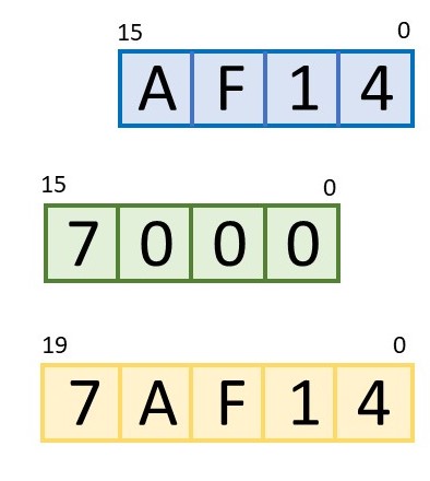
As a programmer, you could make life easy on yourself by loading one register with mostly zeros except for the high-order 4 bits. For example, if you load it with a value like 0x7000 and load the other register with something like 0xAF14, then the two together form the 20-bit address 0x7AF14. Simple!
Things get trickier (for you, not for the processor) if you ignore Rule 1 above and load both registers with full 16-bit values. In those cases, the x86 processor simply adds the two numbers together. It’s not complicated, but it makes the final address harder to figure out in your head.
One side effect of this two-register addressing scheme is that it effectively subdivides the outside world into blocks of 64KB. Your program can access any address within that 64KB block simply by changing one address register, but you have to change two registers simultaneously to move outside of that 64KB block. A lot of compilers had trouble with this. They didn’t really understand two-part addressing,
Another side effect is that you can generate the exact same address in several different ways. That is, different combinations of the two registers will produce the same 20-bit result. Addition is commutative! That also made it hard for software to tell whether two memory references overlapped each other, were disjoint, or were the exact same address specified two different ways. Intel’s memory segmentation solved one problem but spawned some others.
Nowadays, that’s all fixed. Sort of. Intel completely overhauled its memory segmentation scheme in the 1980s with the first ’286 and ’386 chips (back when processors had part numbers instead of names). The nifty thing was, the segmentation system looked the same but behaved entirely differently. That allowed for backward compatibility, which, as we know, is the x86 family’s most endearing feature.
You still use two registers to form an address, and one of those registers (the lower part) even works the same as before. But the upper half – called the segment register – is now a pointer into a memory structure. It’s not added to or concatenated with the lower part at all. That’s much too simple. Instead, it’s an index pointer into a huge table where all the details are stored.
The good news is, the old limitation of 64KB per segment is gone. Now, a memory segment can be just about any arbitrary size at all. In fact, you can fine tune each segment to be any size you want, from 1 byte up to 4GB. You could have a 17-byte segment, a 101KB segment, a 42MB segment, and so on. Very handy.
You also get to define whether each segment is storing code, data, or a stack. And, you can assign each segment a privilege level, so that certain data can be accessed only by certain segments of code. You can even make rules about which code segments can jump to which other code segments. All very nice, and a playground for low-level firmware engineers (and hackers).
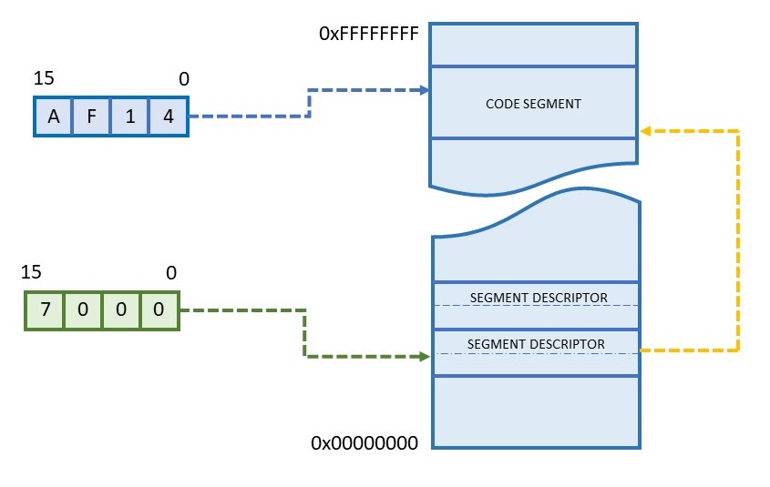
This all works because the segment register itself no longer holds the upper 4 to 16 bits of the address. Instead, that information, plus a lot more, is stored in a 64-bit (eight-byte) structure in memory called a “segment descriptor.” You define one of these descriptors for each memory segment you think you’ll need. At a minimum, you’ll want one code segment, one data segment, and one stack segment. These may or may not overlap (your call), or they might be totally disjoint and point to areas of ROM, DRAM, and SRAM, respectively. Pretty much anything goes.
Each segment descriptor is itself stored somewhere in memory along with all the other segment descriptors. Collectively, this is the “segment descriptor table.” You get to decide where this table resides. Half of each descriptor holds the 32-bit address of the start of the segment. Right off the bat, we’ve removed one of the old limitations that segments always started on 16-byte boundaries. Segments can start and end on any address at all, although you might want to align them on even-numbered boundaries for hardware performance reasons.
What’s the other half of the segment descriptor used for? As Emperor Palpatine says, “a great many things.” Twenty bits define the length of the segment, which gives you single-byte granularity up to 1MB (220). After that, a “granularity” bit in the descriptor converts your length field into units of 4KB, allowing you to define huge memory segments, albeit with coarser size granularity.
That leaves us with 11 more bits to define the type of segment (code, data, stack), whether it’s read-only or read-write, its privilege level (two bits), a bit for whether privileges are enforced for this segment, one for treating this segment as 16-bit code (for backward compatibility), and one for telling the system whether the memory is physically present (which helps with virtual memory and page faults). There’s even a leftover bit for the user. Go nuts.
Most of the limitations of the old segmentation scheme are gone, and a bunch of new features have been added, yet the system looks more or less the same to software. That’s a neat trick, considering how much has changed. It’s entirely possible to set up segment descriptors that describe old-school 64KB segments of memory, and to arrange them in the descriptor table in such a way that 1980s-era software wouldn’t know the difference. Or, you could implement a “flat” memory map with segments that span the entire 4GB address range. The segment registers, index pointers, descriptors, and descriptor table would still exist, but software wouldn’t need to know about them.
For all its weirdness and complexity, Intel’s segmentation system has some real advantages. You can define a segment’s boundaries to tightly encapsulate your code, preventing runaway software from executing beyond the last valid instruction. You can declare data structures write-only, even when they’re in RAM, to stop accidental (or malicious) interference. Code segments have privilege levels associated with them, and the CPU hardware will automatically arbitrate access; no operating system required. You can prohibit self-modifying code simply by not defining a data segment that overlaps a code segment. (Code segments are always read-only.) Conversely, you can enable self-modifying code by defining a segment twice, once as code and once as writable data. Or maybe just portions of the code. Whatever works for you.
Like any power tool, you can get yourself into trouble with memory segmentation. It’s easy to lock yourself out of your own code or stack if you’re not careful about assembling a sensible descriptor table, or by being incautious with access privileges. Most of the x86 family’s hardware bugs were exterminated long ago, but that doesn’t mean we can’t still make mistakes. Some features never go away.


