

Back in early 2024, I discussed SiTime’s MEMS-based temperature-controlled and oven-controlled crystal oscillators (TCXOs and OCXOs) as replacements for ubiquitous crystal oscillators. (See “Adventures with SiTime’s MEMS-based Super-TCXOs – Super Accurate Clocks for the Future – Part 1.”) In that article, I wrote:
“My target instrument for using these SiT5503 Super-TCXOs was a factory-built Heathkit SM-2420 frequency counter purchased from eBay for $40. That 40-year-old instrument is based on a Heathkit-designed OCXO operating at 10.000 MHz. The Heathkit OCXO is a large Styrofoam box containing a heating oven. Inside the oven is a 10MHz crystal. The SiTime Super-TCXO exhibits nearly two orders of magnitude better temperature stability than the frequency counter’s OCXO and needs thousands of times less volume and significantly less power to operate. When the Heathkit counter arrived, it looked like it had been stored in a barn for the last few decades. The circuit board was covered with dirt, and the rotary switch shafts were heavily corroded. The power cord had been cut off. As a backup, I paid $45 for an HP 5314 universal counter, which is based on a now-obsolete Intersil ICM7226A frequency counter/timer on a chip. The HP 5314 also uses an internal 10MHz reference clock, and HP offered the instrument with a TCXO option, but my copy does not have that option. So my HP 5314 also makes a good candidate for a Super-TCXO clock transplant.”
Well, the oscillator transplant has finally taken place. In this article, I’ll describe how I added a Super-TCXO board to an HP 5314A frequency counter. Before getting into the oscillator transplant, however, I feel that I should discuss timing metrology. If you’re going to experiment with precision oscillators, then you need a precise frequency reference. In the past, you might have acquired a cesium or rubidium frequency reference, but those instruments cost hundreds or thousands of dollars. Fortunately, the United States has seen fit to shower nearly every square centimeter of the planet with precise timing information in the form of GPS signals. The precision of these signals is based on atomic clocks.
Inexpensive devices that receive and decode the time from these GPS signals and then output a precise 10MHz timing reference are readily available. They’re called GPS Disciplined Oscillators (GPSDOs). I bought mine on eBay for $83 including tax and free shipping from Shenzen, China. My unit included a GPS patch antenna and cable, but I had to supply the 12V wall wart. You’ll find many listings for this GPSDO on eBay. Just search for “GPSDO” and sort the results by price. The purchase price plus shipping generally ends up at around $80 as I am writing this article.
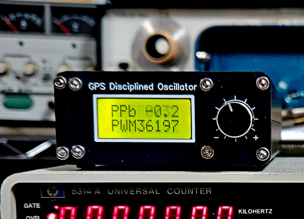
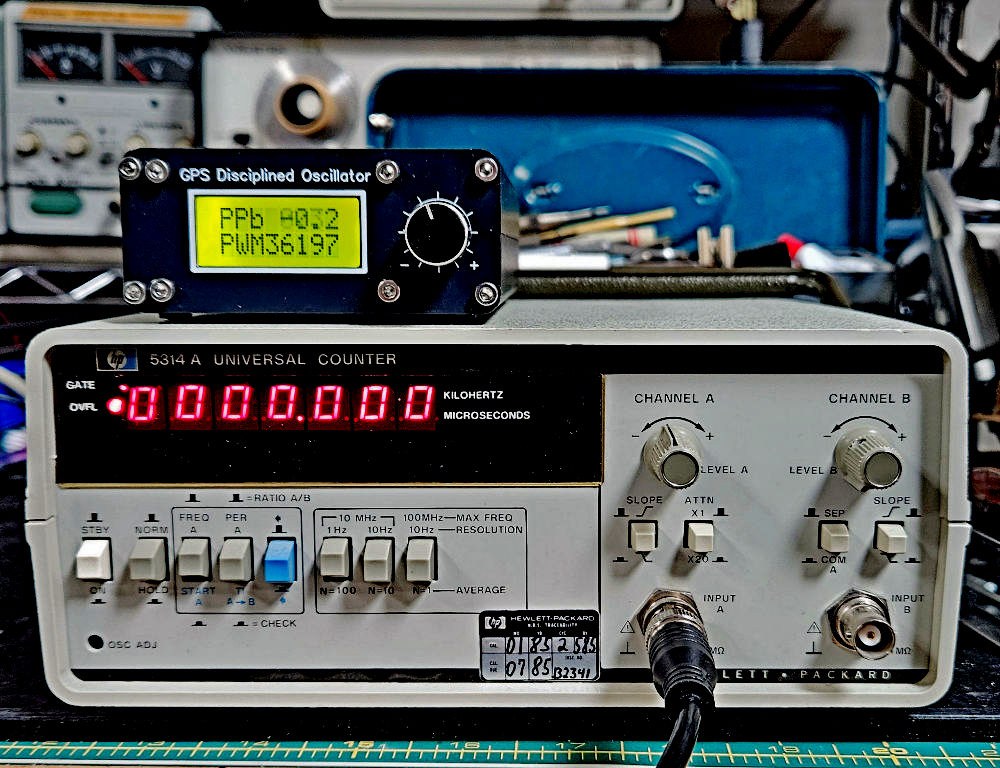
A GPS Disciplined Oscillator (GPSDO) uses time signals from the atomic clocks aboard GPS satellites to precisely adjust the 10MHz output of a local voltage-trimmed OCXO. Image credit: Steve Leibson
My GPSDO was designed by a ham based in China with the call sign BH3SAP. This ingenious GPSDO design has been widely replicated, and it’s easy to see why. The design employs an ST Microelectronics Blue Pill microcontroller board (likely a Chinese copy) that gets a reference 1 pps signal from an integrated uBlox GPS receiver module (likely a Chinese copy) and uses that pulse to gate an internal counter attached to a voltage trimmed OCXO. The Blue Pill microcontroller board then generates an analog control voltage using one of its PWM outputs with a low-pass filter to set the OCXO’s trim-voltage input. Once the GPSDO achieves lock with the GPS satellites, its 2-line LCD displays the real-time accuracy of the unit’s 10MHz output in parts per billion and the 16-bit PWM setting currently being used to achieve that accuracy.
It can take as much as half an hour for the GPSDO to achieve a lock on the GPS satellites, as indicated on the unit’s 2-line LCD. The local OCXO continues to generate a precise 10 MHz signal even if GPS lock is lost. My GPSDO claims to be tracking to less than one half of one part per billion compared to GPS time, and that’s sufficient for my needs. If I position the GPS patch antenna under a skylight, I can operate the GPSDO indoors.
For the price, I don’t think you can beat this low-cost frequency reference. In online discussions, GPSDO owners have seen frequency accuracies of 0.001 Hz. If you’re not satisfied with the stock firmware in the GPSDO, there’s an independently written and greatly enhanced firmware release for the instrument with excellent instructions on github.
My GPSDO gave me the frequency reference I needed to calibrate the HP 5314A frequency counter that I’d purchased from eBay. This counter was designed in 1978 and was documented in a sidebar in an article that appeared in the January 1979 issue of “HP Journal.” The main part of that article describes HP’s bigger, better, and more expensive 5315A and 5316A frequency counters, which are based on a Mostek 3870 microcontroller and two custom LSI parts. The sidebar describing the 5314A frequency counter, written by Michael D Wilson and David M George and titled “Lowest-Cost HP Universal Counter Developed Using LSI and Manufacturing Innovations,” describes an instrument specifically designed for low-cost manufacturing. It’s based on a standard LSI device, an Intersil ICM7226A, which incorporates an 8-decade counter chain, control circuitry, and an integrated 7-segment LED display driver. Earlier HP frequency counters, like most counters of the era, were built with SSI and MSI TTL chips. Intersil’s development of the CMOS ICM7226A collapsed the bill of materials for a high-speed counter, but the 5314A design engineers needed to add a divide-by-ten ECL prescaler to their design because the maximum input frequency of the now-obsolete ICM7226A is a humble 10MHz. The prescaler gets the instrument to 100 MHz.
I eventually bought a second 5314A from another eBay seller. Although HP offered a TCXO option for the 5314A counter, neither of the instruments that I purchased have this option. Instead, they have a board-mounted 10MHz crystal trimmed by a single-turn variable capacitor. I found it very difficult to precisely calibrate the internal reference clock on my two 5314As using the trimmer capacitor, which is accessed through a small hole on the front panel. The 5314A displays only 7 digits and has an overflow LED, so the 10MHz clock signal from the GPSDO should read 0000000 with the overflow LED lit. The tiniest nudge of the trimmer capacitor produced frequency swings of several Hz. As my friend Dave Jones of the EEVblog likes to say, you must get your tongue angle just right when you calibrate these counters.
In addition, one of my two HP counters exhibited quite a bit of medium-term drift after being powered on. I let one unit warm up for 30 minutes and trimmed the capacitor to get a reading of 0000000 on the display. Then I shut the counter down and powered it up a couple of hours later. It gave a reading of 999988. That’s low by 12 Hz. Even with the 5314A’s 7-digit resolution, it’s a noticeable error. After perhaps 15 minutes of warmup time, the counter would read 0000000.
My second 5314A would power up with a reading of 0000000 but would drift to 0000002 after 10 minutes or so. This low-cost counter was not designed to accept an external 10MHz clock, so both counters would benefit from better internal oscillators. Given their 7-digit resolution, plus the overflow LED, I needed to install an oscillator with an initial accuracy of at least 100 parts per billion and low drift over time and temperature.
The Super-TCXOs supplied to me by SiTime fit these requirements very well. They are fixed-frequency oscillators, and their output frequency is trimmed at the factory. The particular Super-TCXOs that I received from SiTime cannot be trimmed in the field, but the company sells field-trimmable Super-TCXOs as well as MEMS-based OCXOs. The factory-trimmed Super-TCXOs I received were accurate enough to serve as an internal reference for the HP 5314A’s 7-digit resolution, although they’re not sufficiently accurate for the Heathkit IM/SM-2420’s 8-digit resolution. Consequently, I decided to install the Super-TCXO boards that I’d designed for Part 1 of this article (and laid out by my friend Ron Sartore) in at least one of my two HP 5314As.
The clock input on the ICM7226A counter chip requires a minimum high-level input voltage of 3.5V, which the SiTime Super-TCXOs cannot supply because they operate on a 3.3V power supply. In Part 1 of this article, I’d experimented with using a 74HCT00 quad 2-input NAND gate as a buffer and voltage shifter but have since migrated the design to use one gate in a 74HCT14 hex inverter, mounted dead-bug style on the circuit board and wired by hand. If I were redesigning this board for production, I’d likely use a single 74HCT gate in a smaller package, such as a Texas Instruments SN74AHC1G14DBVR, but I used what was readily available on eBay for this prototype. The completed Super-TCXO board installed in the 5314A counter appears below.
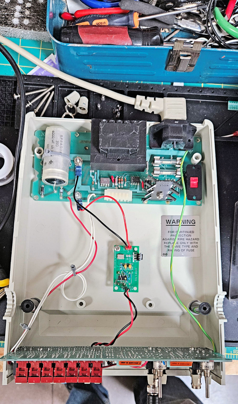
This photo shows the inside of an HP 5314A frequency counter, which is mostly filled with air. The original power supply board appears at the top, the logic and display board appears at the bottom, and the Super-TCXO board appears in the center. Image credit Steve Leibson
Because the 5314A counter was designed to accept a TCXO option, installing a new oscillator board in the instrument was fairly easy. The 5314A’s original power supply board, which appears at the top of the above photo, had a pair of large pads for +5V and ground. These pads are intended for the 5314A’s original TCXO option, so I simply crimped some terminal lugs onto a 2-pin, 0.10-inch cable assembly and bolted the lugs onto the power supply board with 6-32 mounting hardware. An existing and very convenient mounting post with a tapped, 6-32 metal insert in the center of the instrument’s case served as the single mounting point for the lightweight Super-TCXO board. A second 2-pin, 0.10-inch cable carries the 10MHz clock from the Super-TCXO board to the existing logic board, where it’s soldered into two existing pads designed for HP 5314A’s original TCXO option. Installation of the Super-TCXO board required less than 30 minutes including the desoldering of a jumper wire on the logic board to disconnect the existing crystal oscillator from the ICM7226A counter chip’s clock input.
After the installation, the 5314A counter powered up and displayed precise frequency readings of the GPSDO’s 10MHz output (showing 0000000 with overflow set) in much less than a minute. Thanks to SiTime’s factory trimmed Super-TCXO, no calibration trimmer capacitor or potentiometer is needed. I have not yet upgraded my second HP 5314A frequency counter, but I have a second Super-TCXO board ready for transplant. I also purchased the last and only ICM7226A counter IC that I could find from Anchor Electronics in Santa Clara, California. These devices have been obsolete for years and are now very hard to find.
In my next EEJournal article, I will discuss the extensive refurbishment of two Heathkit IM/SM-2420 frequency counters.

