

Clocks are integral to most electronic systems. Timing and communications systems need extremely accurate clocks. When I started working with electronics, in the heyday of Citizen’s Band (CB) radio, quartz crystals were on sale everywhere, even at Radio Shack. The CB crystals congregated around 27 and 28 MHz, but many more frequencies were on offer. As I started designing circuits as an engineer, I used many specific crystal frequencies: 32.768 kHz for real-time clock circuits, 3.57954 MHz for the TV color burst, 1.8432 MHz for the Motorola MC14411 bit-rate generator, 4.9152 MHz for the bit-rate generator in the Signetics 2661 enhanced communications chip, and frequencies such as 4.00, 8.00, 10.00, 20.00, 33.33, and 50.00 MHz for clocking early microprocessors of the 1970s and 1980s. In my first engineering job at HP’s Loveland, Colorado facility, I could get any crystal frequency I needed in just a few days from Colorado Crystal, which was located five minutes away from the HP plant. Colorado Crystal, founded in 1968, is still there in the same Loveland location on 8th Street.
As long as I’ve been an engineer, it’s always been a crystal. Quartz crystals have been used for precise frequency control of electronic circuits for the last 100 years. So, I never gave much thought to the use of crystals for precision frequency control. They were simply the standard component for generating precise frequencies. My colleague Max Maxfield recently wrote about some new oscillators from SiTime (see “It’s Time to Learn More about Timing”) based on MEMS (micro-electro-mechanical systems) structures. Max’s article renewed my interest in frequency generation for digital circuits. I visited SiTime in Santa Clara California several years ago when the company first started making MEMS-based oscillators. Max’s article shows that they’ve considerably evolved and improved their product. SiTime’s entirely different approach uses vibrating, MEMS-based, silicon structures to create precise oscillators that could put the industry on a path to eliminating crystals from the EE vocabulary. Crystals could join selenium rectifiers, wax-and-paper capacitors, tubes, and germanium transistors as components that have largely or entirely been replaced by a superior technology.
Pierre and Paul-Jacques Curie, working at the Sorbonne’s Laboratory of Mineralogy in Paris, discovered the piezoelectric effect in 1880. It’s that fundamental effect that allows quartz crystals to resonate at precise frequencies. Quartz crystals were first used to stabilize the frequency of an electronic oscillator in 1917 and 1918, respectively, by Alexander Nicholson at the Bell Telephone Laboratories and Walter Guyton Cady, a physics professor at Wesleyan University. In 1923, August E. Miller started selling quartz crystal blanks to amateur radio operators (hams), who then used Miller’s blanks to make their own finished crystals for stabilizing the operating frequency of their radio transmitters.
It appears that hams did most of the early practical circuit development for crystal-stabilized radio transmitters. Several circuits for crystal-controlled transmitters appeared in QST magazine during 1924 and 1925. (QST has been published by the ARRL (American Radio Relay League) for hams since December 1915.) By August 1925, General Radio was offering finished quartz crystals for specific frequencies at $35 to $50 each, depending on the desired accuracy. In 1926, AT&T’s WEAF became the first commercial radio broadcasting station to set its transmitter frequency with a quartz crystal. Finally, in 1939, the US military adopted crystal control for its radios, just in time for World War II. After the war, this military technology helped to kick off the CB and walkie-talkie craze. (Max Maxfield covered some of this history in his previous article titled “MEMS Oscillators Address Precision Timing Problems”.)
Over the next 97 years, quartz crystals and crystal oscillators became the pervasive component of choice for precise frequency control in every facet of electronic circuit design. Now, SiTime is ready to change that. SiTime’s oscillators do not use the piezoelectric effect. Their timing comes from precisely machined (etched) MEMS structures with resonant mechanical frequencies. Max’s article described a new OXCO (oven-controlled crystal oscillator) from SiTime based on the company’s Epoch Platform, which uses two MEMS structures. The first structure is a mechanical resonator designed to have a flat frequency response curve with respect to temperature. The second MEMS structure is another resonator that’s designed to act as a temperature sensor. (SiTime describes it modestly as “the world’s most accurate temperature sensor”.)
The two MEMS structures are etched into one piece of silicon, and their output signals feed a second CMOS chip, which contains the oscillator’s active circuitry. Oscillation frequency is based on feature sizes defined by precise silicon photolithography and anisotropic etching. SiTime markets these devices as either Super-TCXOs (temperature compensated crystal oscillators) based on its Elite platform or, with the addition of a heater, as OXCOs based on the company’s Epoch platform. Note that SiTime is reusing quartz-based oscillator terminology to avoid confusion as to what the company’s parts do, but there are no quartz crystals inside of SiTime’s parts.

SiTime’s latest TCXOs and OXCOs are based on the Epoch Platform, which incorporates two MEMS structures: a mechanical resonator designed to have a flat frequency response curve with respect to temperature and another resonator that the company describes as “the world’s most accurate temperature sensor.” A second CMOS chip in the package contains the oscillator’s active circuitry. Image credit: SiTime
I wanted to experiment with this once-in-a-century revolution in frequency control, so I asked SiTime for sample parts. Initially, I asked for OXCOs, having a specific project in mind. However, the new SiTime OXCOs appear to be wildly popular, and no OXCO samples were available, so I agreed to try out some SiT5503 Super-TCXOs instead. I’ve always been fascinated by frequency counters, which precisely measure signal frequencies, yet they incorporate only one precision component: the timing crystal. Usually, these timing crystals operate at 10 MHz, so I requested 10MHz devices from SiTime, and the company sent me two sample devices with the part number: SiT5503AI-WW-33E0-10.000000. Using the decoder on the SiT5503 data sheet:
- “SiT5503A” – Device family
- “I” – Industrial temperature range, -40 to 85°C
- “–“ – LVCMOS output
- “W” – Package size (7.0 x 5.0 mm)
- “W” – Frequency stability, ±5 ppb
- “33” – 3.3V power supply
- “E” – Output Enable pin
- “0” – Fixed frequency output
- “10.000000” – Operating frequency in MHz
Note that SiTime programs the operating frequency of these devices at the factory.
My target instrument for using these SiT5503 Super-TCXOs was a factory-built Heathkit SM-2420 frequency counter purchased from eBay for $40. That 40-year-old instrument is based on a Heathkit-designed OXCO operating at 10.000 MHz. The Heathkit OXCO is a large Styrofoam box containing a heating oven. Inside the oven is a 10MHz crystal. The SiTime Super-TCXO exhibits nearly two orders of magnitude better temperature stability than the frequency counter’s OXCO and needs thousands of times less volume and significantly less power to operate. When the Heathkit counter arrived, it looked like it had been stored in a barn for the last few decades. The circuit board was covered with dirt, and the rotary switch shafts were heavily corroded. The power cord had been cut off. As a backup, I paid $45 for an HP 5314 universal counter, which is based on a now-obsolete Intersil 7226 frequency counter/timer on a chip. The HP 5314 also uses an internal 10MHz reference clock, and HP offered the instrument with a TCXO option, but my copy does not have that option. So my HP 5314 also makes a good candidate for a Super-TCXO clock transplant.
When the SiTime Super-TCXOs arrived, the FedEx package contained two SMT parts. Clearly, I needed a circuit board. For that, I turned to my good friend and frequent collaborator Ron Sartore. I’ve known Ron since 1988 when I engaged him in another hands-on electronics project. Back then, Ron’s company, Cheetah International, made the fastest IBM PC motherboards on the market. These days, Ron’s semi-retired, but his company, Altimeter Motives, makes realistic instrument panels for use with flight simulators such as Microsoft Flight Simulator and X-Plane. Ron has a license for the Eagle pcb layout software and an established relationship with JLCPCB, a fast turn pcb manufacturer in China.
I laid out a simple schematic for the Super-TCXO board:
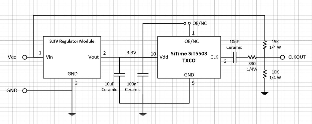
Schematic for SiTime Super-TCXO board. Image credit: Steve Leibson
Because my target application was a 40-year-old Heathkit frequency counter, the supplied operating voltage would be 5V, but my SiTime SuperTCXOs needed 3.3V, so I used an LDO regulator module from Amazon to convert the 5V to 3.3V. Fifteen of these modules cost $9 and have a TO220 footprint, so they’re similar to using 7800 series regulators, but note that the pinout is different. (Please do not ask me how I know. Just look for the magic smoke above my workbench.)
Next, I needed to convert the Super-TCXO’s 3.3V output to something more TTL compatible, so I reused a passive level-shifter circuit from an HP 5314 frequency counter. Ron kindly created a pad stack for the SiTime Super-TCXO’s unique package, laid out the pcb in Eagle, and sent it to JLCPCB for fabrication. I ordered 10 blank pcbs for just under $25, delivered, so each double-sided board cost me about $2.50. When they arrived from China, Ron took the two Super-TCXO samples provided by SiTime and built up two boards, one with the Super-TCXO and all the components shown in the above schematic and one without the passive level-shifting network. Ron’s lab has equipment for SMT assembly. Mine does not.
The Super-TCXO board with the passive level shifter worked as designed, but the shifted output level was barely enough for the Intersil 7226 counter chip’s clock input, and it was sensitive to the 5V level of the power supply, so I took the second built-up Super-TCXO board and added a 74HCT00 quad NAND gate directly to the Super-TCXO’s output, dead-bug style, using the board space previously occupied by the passive level-shifting network. I bought the 74HCT00 from my favorite Silicon Valley electronics surplus store, Anchor Electronics. They cost $0.22 each in unit quantity. It turns out that 74HCT devices are ideal for converting 3.3V signal levels to 5V logic levels. If I were designing this board for production, I’d use a single-gate SMT device like a 74AHCT1G08 from Texas Instruments, NXP, or Diodes Incorporated for level translation. The modified board also worked well. Both boards were oscillating bang on at 10.000000 MHz, based on the instrumentation available to me. The two built-up boards appear in the figure below. Ron Sartore labeled the board “Steve’s TCO,” but it’s his layout.
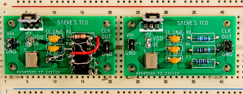
Ron Sartore and I built up two boards based on SiTime’s Super-TCXOs. The Super-TCXOs, measuring just 7.0 x 5.0 mm, are mounted at the lower left of each board and the 3.3V LDO regulator modules appear at the upper left. The board on the left uses a 74HCT00, mounted dead-bug style, to shift the Super-TCXO’s 3.3V levels to 5V. The board on the right uses a passive level-shifting component network. Image credit: Steve Leibson
SiTime also sent me their standard evaluation board for the SiT5503 Super-TCXO. The company offers some Super-TCXOs and OXCOs with an I2C interface that can be used to pull the operating frequency a few ppm either way. The eval board that SiTime sent to me incorporates a full-featured Super-TCXO and has a series terminated clock output with an SMA connector. The board also provides access to the I2C frequency control through additional connectors. I can easily envision using a microcontroller with a timer/counter and an I2C interface, a GPS receiver’s 1pps output, and one of SiTime’s Super-TCXOs or OXCOs to create a GPS-disciplined oscillator (GPSDO).
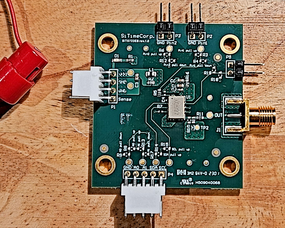
The SiTime evaluation board for the SiT5503 Super-TCXO breaks out all the pins on the oscillator, which is located at the board’s center. Image credit: Steve Leibson
All three oscillator boards produce precise 10MHz clock waveforms. I have two candidate frequency counters for oscillator transplants: an HP 5314 universal counter in near-mint condition and the severely weathered Heathkit SM-2420 counter. It remains to be seen whether the Heathkit counter can be revived, so that’s a story for another article. Meanwhile, check out SiTime’s MEMS-based oscillators next time you’re thinking of using a quartz crystal.
Reference:
Patrick R. J. Brown N7KRG, “The Influence of Amateur Radio on the Development of the Commercial Market for Quartz Piezoelectric Resonators in the United States,” Proceedings of the 1996 IEEE International Frequency Control Symposium (pp. 58 – 65)


Hi Steve — great article — I’ve seen that magic smoke so many times myself that my nose tingles just thinking about it. I think this is the first time I’ve seen a DIL chip mounted “dead bug style” — I don’t know why, but it has never struck me to use that technique — I really hope you can bring the Heathkit SM-2420 counter back to life — I look forward to reading more in the future — Max
I majored in physics at Wesleyan my junior and senior years 1968-1970, so I inspected some of Cady’s devices in the attic of the physics department’s Scott Laboratory. Thanks for this article and for your reference to Colorado Crystal still manufacturing custom crystals. Bliley also still manufactures custom crystals.
Thanks for sharing your memories, traneusee. I think there are many lost wonders rattling around in the attics and basements of the physics departments in universities across the country. My own alma mater, Case, was the site of the Michelson-Morley experiment in 1887, which is famous for being unable to detect the aether that was thought to permeate space and for inadvertently providing experimental proof of Einstein’s Theory of Relativity in 1905. That experimental setup used a 2-arm interferometer to detect the speed of light in orthogonal directions. The LIGO gravity wave observatory uses a related principle. The experiment was conducted in Adelbert Hall, where I studied physics at Case.
“Einstein’s Miraculous Year”, edited and introduction by John Stachel, Princeton University Press, 1998, contains translations of Einstein’s dissertation and four papers published in 1905. All are clearly written (the editor notes occasional errors) using algebra and basic calculus. Dissertation and first paper calculates now many molecules in a mole. Second paper derives special relativity. Third paper derives E=M*c^2. Fourth paper derives the existence of the photon. Einstein’s general relativity dates from 1915. Einstein was awarded the Nobel Prize in physics in 1921 for the photon.
No kidding, Steve, you graduated from Case? When were you there? I got my BSEE there in 1988 and then came out to Southern California and have been here ever since. I remember well the big deal about the Michelson-Morley Centennial Celebration (M2C2) back in 1987, although I thought it was 1986. The Internet proved you correct and me wrong. Well, almost 40 years ago anyway. We students got sick of hearing about the M2C2 back then!
As far as time and frequency measurement goes, I have a store-bought Leo Bodnar GPSDO in my garage lab (about $150) and a Chinese (before I stopped buying anything from China unless I’m forced to do so due to availability) distribution amp for less than $100. For <$250 these days you can have basically an atomic clock to run your instruments! At the moment, I have an HP 8566A spectrum analyzer, HP 5343A frequency counter, and an Advantest VNA (I forget the model number) locked to the GPSDO. More to come, to the chagrin of my wife!
Interestingly enough, at work at Raytheon, we have millions of dollars of equipment, but the benches just use one of the oscillators inside one of the signal generators, presumably an OCXO, and we just daisy chain the 10 MHz to each other instrument's reference input. Kind of sloppy if you ask me, and it's quite easy to get 10 MHz suckouts on a few meters of coax and see the dreaded Reference Unlocked message pop up on one of the sig gens.
And speaking of sig gens, even the relatively new Keysight PSGs we have are big and heavy and only produce one sinewave at a time. The price is probably hundreds of thousands of dollars, which might almost make a decent down payment on a house here in California! Now there are HPAK 8340s and 8672s out there for reasonable prices, but again, the size and weight are prohibitive, and again, it's a single sinewave.
So I have this idea to build a multiple output synthesizer based on an optoelectronic oscillator. The idea is to use a long optical fiber, say 10-20 km, as a low-loss delay line of tens of microseconds as the basis of an extremely low phase noise master oscillator at say, 20 GHz and then divide it down and offset it with a DDS. Replicate the dividers and DDS several times and stick it all inside a 1U or 2U rack mount chassis. Presto, a low SWaP-C synthesizer with multiple outputs! Well, in my spare time (yeah, right!) I'll just whip one up! May have to wait for retirement, whenever that happens…
Well, I'm rambling again. Good to hear from you, Steve.
Jim Ford
CIT '88
Laguna Hills, CA (home)
El Segundo, CA (work)
I graduated more than a decade before you did, Jim. Looks like you’re way more into fequency control than I am. I’ve no spectrum analyzer, save for the software built into my Siglent scope. I’ve always thought the idea of syncing hundreds of thousands of dollars worth of high-end test gear with a 10MHz clock is a bit strange, but it seems to work. Anyway, an embedded guy like me just needs a good clock and a star to steer her by.
Well, I’m an RF and microwave guy who works in radar currently and used to do comms for many years, so frequency control is a big deal for me. It blows my mind how test equipment that used to cost tens of thousands of dollars has depreciated to next to nothing, if not nothing at all. It is, as a friend of mine says, a golden age for test equipment acquisition! I figure there are 3 ways to get gear cheap: 1) the older, obsolete stuff that companies can’t get maintained, repaired, or calibrated is available on eBay, craigslist, etc. for pennies on the dollar, 2) the newer stuff leveraging Moore’s law and modern manufacturing and the PC and USB is pretty reasonably priced, and 3) for those of us with the knowledge and experience, the semiconductor companies’ eval boards are a rich source of DIY gear. Think about it; the semis don’t make any money on the eval boards; they’re just trying to get you to design in their chips into your system. Eval boards even for chips up into the millimeterwave range are a few hundred dollars each at Mouser or Digi-Key. The only limitations I have are time and my wife’s patience with my obsession!
Regarding 10 MHz as a frequency standard, I guess it makes sense. It’s low enough that the cable loss is low, so you can run it fairly long distances. Hams tell me it’s annoying, though, because it’s right in the middle of the HF band and receivers can get swamped out easily if you aren’t careful to use all threaded connectors and shielded cables.
I’m trying to get into ham radio; it’s just a matter of finding the time to get my license and a rig. I already have a 70 cm band (420-450 MHz) antenna up on my chimney and 75 feet of LMR400 coax running down into my garage. A ham friend tried hooking up a handheld VHF/UHF rig to it a few months ago, and we were able to receive from a few hundred miles away, but his transmitter may not have been working because he didn’t get any replies. Someday soon when I’m not working 12-hour days….
Hi Steve,
Very nice article and I’m looking forward to Part 2. Also Max’s articles on the MEMS based oscillators are very well written and very informative.
However, what really got me were the words, “…my first engineering job at HP’s Loveland, Colorado facility.”
My dad worked at HP’s Loveland Instrument Division, first in the PC shop and then in the IC group, for over 20 years. He was a single parent and so as a kid I spent many an evening and occasional weekend in the chem lab pretending to help him but actually just playing around with the cool things in the lab, roaming the halls, or playing ‘Gravity’ on a 9845C. Years later, in between graduating from CSU and going back for extra punishment at CU, I interned for a summer at LID and got to play around with problems on the 3458A voltmeter while working with some really, really good engineers.
Ok, but enough of Streisand humming ‘Memories’ in my head, let’s get down to business:
Don’t write off crystals just yet because as good as SiTime’s Elite and Epoch MEMS platforms are, their close-in phase noise is quite a bit higher than that of top of the line crystal based OCXO’s. For example at 100 Hz offset the noise density of a 100 MHz SiT5812 Epoch ‘OCXO’ is -117 dBc/Hz. Meanwhile a crystal based 100 MHz OCXO from Wenzel has a noise density of -138 dBc/Hz at 100 Hz offset from carrier. This noise is critical and will eat your lunch when the the OCXO is the frequency reference in PLL based systems used to generate higher frequencies.
That said the MEMS oscillators are INCREDIBLY stable – 30 ppb drift (3 Hz @ 100 MHz) over a period of ONE YEAR! while the crystal OCXO’s will drift +/- 10’s of Hz in several hours.
The goal is to get the best of both worlds (and that’s why I’m using the Epoch OCXO’s): Lock the ultra-low noise (but high drift) crystal OCXO’s to the not-so-great noise, but incredibly low drift MEMS oscillator.
Genius, right? Yea, well I’m sure I’m about the 398th person to come up with that idea. The trick is to get the phase lock loop right so that the crystal OCXO follows the MEMS’s low drift, but not its high noise!
Take care and all the best,
Tony
Thanks for the comment, Tony Rohlev. I’m afraid I never ran into your dad, although I interacted a lot with the PC shop and LID built a custom, laser-trimmed resistor network for my last HP product. I’ve never needed to worry about phase noise in a crystal oscillator. I’ve only used them to clock embedded projects. Precision and stability were always top of my care-about list. Phase noise wasn’t on that list at all. that doesn’t mean crystals are on their way out. Often, they’re the least expensive way to solve a problem. For example, a 32,768Hz clock crystal is 18 cents at Digi-Key right now. Eighteen cents! That crystal’s not going away soon.