

I have been building up my home lab these past few years, and I decided that I needed a better multimeter. My original Fluke 77 handheld digital multimeter (DMM) has served me well for more than 40 years, but I wanted more resolution than its 3½ digits. A few years back in a fit of GAS (gear acquisition syndrome), I purchased a 20,000-count Surpeer AV4 multimeter from Amazon for $40. Alas, the Surpeer is no longer available. Eventually, I wanted a faster meter—a bench meter—so I purchased a dead Keithley 179 for $20 from eBay (plus $20.30 for shipping and tax) and described its resuscitation back in 2024. (See “The Case of One Dead Digital Multimeter” for an extended description of the Model 179 DDM’s repair and a history of Keithley.)
Eventually I wanted more resolution, so I purchased a 220,000-count Keithley 197 on eBay for $85 (plus $6 for sales tax). It appeared to be in very good shape based on the auction listing photos, and when I received it, the DMM seemed to measure voltages accurately, so I considered it a fortunate purchase.
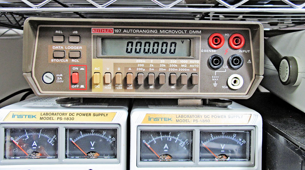
Keithley’s Model 197 DMM is more than 40 years old—the Rev A schematic is dated 5-31-1984. This DMM was a high-end product in its day. On its lowest range, the Keithley 197 measures 200 mV full scale, with 1 μV resolution (thanks to its 220,000-count spec), so Keithley marketed the Model 197 as the “Microvolt DMM.” (It says so right on the cover of the Model 197’s manual.) Perhaps 1 μV resolution isn’t so impressive these days, but 40 years ago, it was hot stuff. Even today, I cannot foresee needing to make sub-microvolt measurements in my modest home lab.
In addition, the Model 197 was one of Keithley’s earliest microprocessor-controlled, software-driven multimeters. It’s based on an 8-bit Motorola MC146805E2 microcontroller, a ROM-less CMOS variant of Motorola’s very successful 6805 microcontroller family. The internal microcontroller runs the show inside the DMM. The microcontroller controls the A/D conversion, operates the display, and handles instrument calibration, which is stored in an on-board NVRAM. However, the meter still relies on a bank of ganged mechanical pushbutton switches for selecting the quantity to be measured (volts, amps, and ohms) and the range.
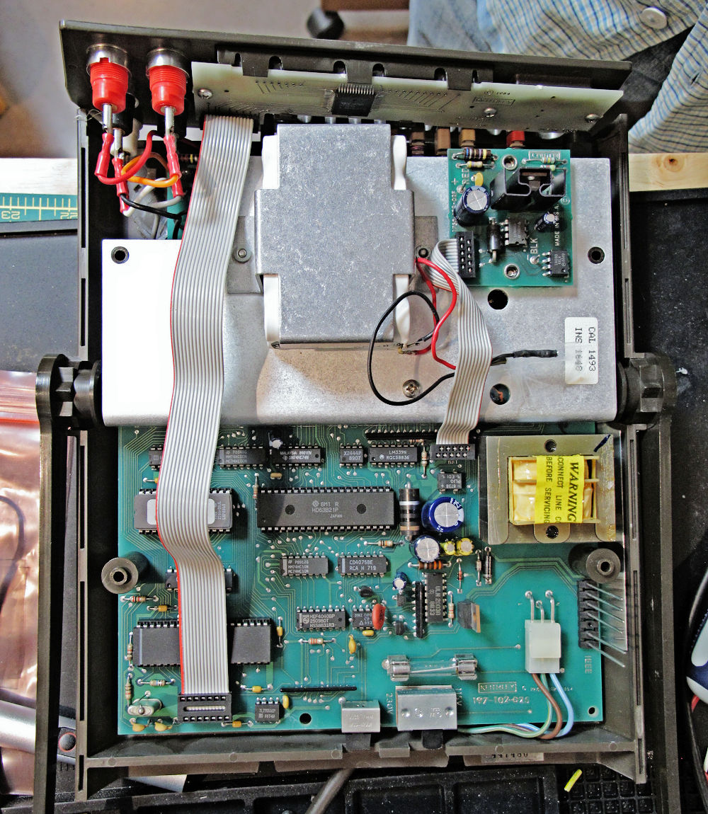
The Model 197 was one of Keithley’s earliest microprocessor-controlled, software-driven multimeters, based on a ROM-less, 8-bit, Motorola MC146805E2 microcontroller. The microcontroller is hiding under the display cable in the lower left of this photo: Image credit: Steve Leibson
My copy of this venerable instrument from an eBay seller was relatively clean and, unlike many other similar Keithley meters from this era offered on eBay, the plastic case and carrying handle were in good shape. Many Keithley multimeters from that era (late 1970s through the late 1980s) advertised on eBay have large chunks missing from their plastic cases, and most are missing their carrying handles. My copy of the Model 197 appears to have been manufactured in 1988, based on the date codes printed on its ICs.
Despite its relatively good condition, I had two major gripes with my new Keithley 197 multimeter. First, the meter’s reflective LCD is hard to read in low light. Duh, it’s a reflective LCD. However, the Keithley 197’s plastic case has a large overhang at the top that shadows the LCD, preventing it from getting much light from ceiling or overhead illumination. Keithley fixed this problem with the Model 197A, which has a proper LCD backlight, but I have an earlier non-“A” model. There’s a terrific hobby project on github that mates a modern OLED display to a Model 197. It’s a tour de force design that uses a Microchip AVR64DB28 microcontroller running an Arduino sketch to decode readout data streamed from the Model 197’s motherboard, which the author—alx2009—reverse engineered. The AVR microcontroller translates the decoded display information and sends the translation to the OLED display. The result is a beautiful and modern display with extra features that nicely update the 40-year-old design.
The EEVblog Forum has a long discussion about alx2009’s project with photos. It’s truly an awesome project that would make a great retrofit kit, but, without a premade kit, it requires far more effort than I wanted to expend for my DMM. My initial solution to this problem is to strategically position a Harbor Freight rechargeable, right-angle flashlight that I attach magnetically to the shelving beside the DMM. This solution is effective, but it’s a temporary one. Eventually, I’ll come up with something better. I have a frontlighting experiment for the LCD in mind, but that’s another story for another day. For now, a flashlight with a magnetic base will suffice.
My other gripe turns out to be a common problem with these meters and similar Keithly meters like the model 175. Because these instruments are now four decades old, the four rubberized pushbuttons on the front panel—used to make relative measurements, dB measurements, and for the data logging function that stores and recalls readings—no longer worked. The meter is perfectly usable without these buttons, but eventually, I decided that I wanted to fix this problem.
My first pushbutton repair attempt was to try to re-impregnate the carbon contacts on the back of the rubber buttons using powdered graphite. I had a handy tube of graphite lube that I use for freeing up door locks, so I put a couple of graphite puffs into a pill bottle cap and used a cotton swab to dab graphite on the four carbon contacts. I found this approach discussed in a YouTube video on the “Julian Does Stuff” channel that describes the repair of television and AV receiver remote controls.
The method seemed immensely successful in the video, but I was not able to find a happy medium between not enough graphite, which produced no result, and too much graphite, which produced buttons that were always on because the carbon button contact left too much graphite on the target pc board. I then decided to try soldering tactile switches over the interdigitated pc board fingers that serve as the landing targets for the four carbon contacts. This solution would insert switches that were actually designed to be switches into the design and would resolve another objection I had to Keithley’s original design by adding a tactile feel and an audible click to each switch, thus getting rid of the original rubber buttons’ mushy feel.
The trick was to find a switch that fit the existing finger footprint while fitting within the outline of the rubber button. In the hopes that the right switch might be found in a large assortment of small tactile pushbutton switches, I purchased a 375-piece switch assortment from Amazon for $15. (That’s four cents per switch.) The kit contains 26 tactile pushbutton types ranging in size from 3x6x2.5 mm to 12x12x7 mm. As it happened, the 3x4x2mm switch seemed to fit exactly within the open envelope beneath the Keithley 197’s rubber buttons.
First, I hot glued the tactile switches in place, because the switch alignment is critical in this retrofit situation. The switch must be centered on the pc board’s interdigitated finger pattern (the original target for the carbon contact) to fit within the cavity under the rubber button, and it needs to be short enough to fit between the pc board and the rubber button’s carbon contact. After I was satisfied with all four switch alignments, I soldered the four switches in place using a solder flux pen and a spool of small-diameter solder. I used my 50-year-old Weller soldering station, which is suitable for the modification of this 40-year-old multimeter.
As I heated one switch contact tab on each switch with the soldering iron, the heat of soldering melted the hot glue and I pressed down on the switch to fully contact the underlying pc board. However, the hot glue initially failed to adhere to the pc board traces, so I had to sand the interdigitated fingers on the board to roughen them up a bit and then reapply the hot glue. Alignment was good enough so that I needed no extra wire for five of the eight soldered connections (two per switch), but three of the connections weren’t sufficiently aligned to allow solder to flow from an electrical tab on the switch to the corresponding pc board trace. I was off by only fractions of a millimeter, but that was sufficient to require a bit of extra interconnect wire. After soldering the four switches to the board, I checked the connections and the switch action with an ohmmeter (my trusty Fluke 77 handheld multimeter, which I obtained in 1985).
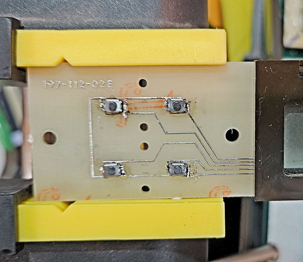
I upgraded my Keithley 197’s front panel pcb with four tactile switches to replace the failed rubberized buttons. The switches are so small that they fit entirely inside the rubber buttons, with the addition of 1mm spacers to allow the buttons to pop back out after being pushed. Image credit: Steve Leibson
After reattaching the Keithley 197’s display pc board to the front panel, I tried out the new tactile switches. They pressed in just fine with a very satisfying click. However, the tactile switches lacked sufficient force to return the button to its home position after I stopped pressing on it. As an experiment, I backed out the three 6-32 screws that attach the display board to the front panel by a turn or two, and the buttons immediately snapped back into the home position. Based on that result, I was confident that a small washer between the display board and the front panel would solve this new problem. I found three suitable 1mm-thick nylon M3 washers in an assortment of plastic spacers that I’d purchased from Amazon a couple of years ago. The 1mm washers did the trick, and the rubber buttons now freely returned the rubber buttons to their home positions. With everything checked out and working, I reassembled the multimeter, tested it, and returned it to its place on my workbench. I now have 371 tactile switches left in my assortment kit.
Meanwhile, my Keithley 179 multimeter had failed—again—and its display was behaving very oddly, so there’s a Part 2 to this story.


