


Commercial EDA companies started to appear in the 1960s, and a trend of sorts was set. In each new, more advanced generation of EDA tools, three companies tended to dominate. The first EDA generation was the era of digitization. Computers and digitizers started to displace drafting tables and mechanical drafting machines in all engineering disciplines including electrical and electronic engineering. The dominant EDA trio in this CAD (Computer Aided Design or Computer Aided Drafting) era consisted of Calma, Computervision, and Applicon.
Before delving into the history of these three pioneering companies, it’s important that you understand the state of electronic design back in the early 1960s. You have no doubt seen photographs of large engineering bullpens filled with drafting tables and mechanical drafting machines. Although most of those photos represent mechanical, aeronautical, and civil engineering operations where cars, airplanes, and structures were designed, electronic design was similar. An engineer would start an electronic design by drawing a block diagram or a schematic on large sheets of vellum paper using a mechanical pencil and an eraser. From there, the design might become a printed circuit board or, eventually, an IC. The schematic design would then be converted into a physical layout by a circuit board or IC layout designer.
Before CAD systems appeared, multi-layer circuit boards would be developed by hand-taping the traces using black paper crepe tape and pre-cut adhesive pads. Bishop Graphics was a major supplier of these layout materials. Eventually, Bishop Graphics and its competitors started to produce patterns for popular components such as transistors and DIP ICs. These multi-pad patterns helped to speed board design, but it was still a slow, error-prone, manual process. (Note: I used these products to design circuit boards in high school during the 1960s and early 1970s.) Hand-taped boards are distinctive. There are usually no straight circuit traces on these boards, just curved ones.
IC designs required more precision to produce the photographic mask layouts. IC layout people became adept at cutting mask designs from a material called peel coat. The most famous brand of peel-coat film was Ulano Corp’s Rubylith, which had become quite popular in the commercial graphics industry, a much larger industry than chipmaking back in the 1960s.
IC mask designers became proficient in cutting and peeling sheets of Rubylith to produce enlarged photolithographic masks, which were then optically reduced to life-size for IC fabrication. It took a steady hand and intense concentration to wield the X-Acto knife while cutting Rubylith. Like patternmaking for circuit-board layers, IC mask-making was a slow, error-prone, manual process. Fortunately, back in the 1960s, ICs needed very few masks. However, as ICs became larger and the number of mask layers increased, there was growing pressure to automate the entire process. The same was true for circuit board fabrication.
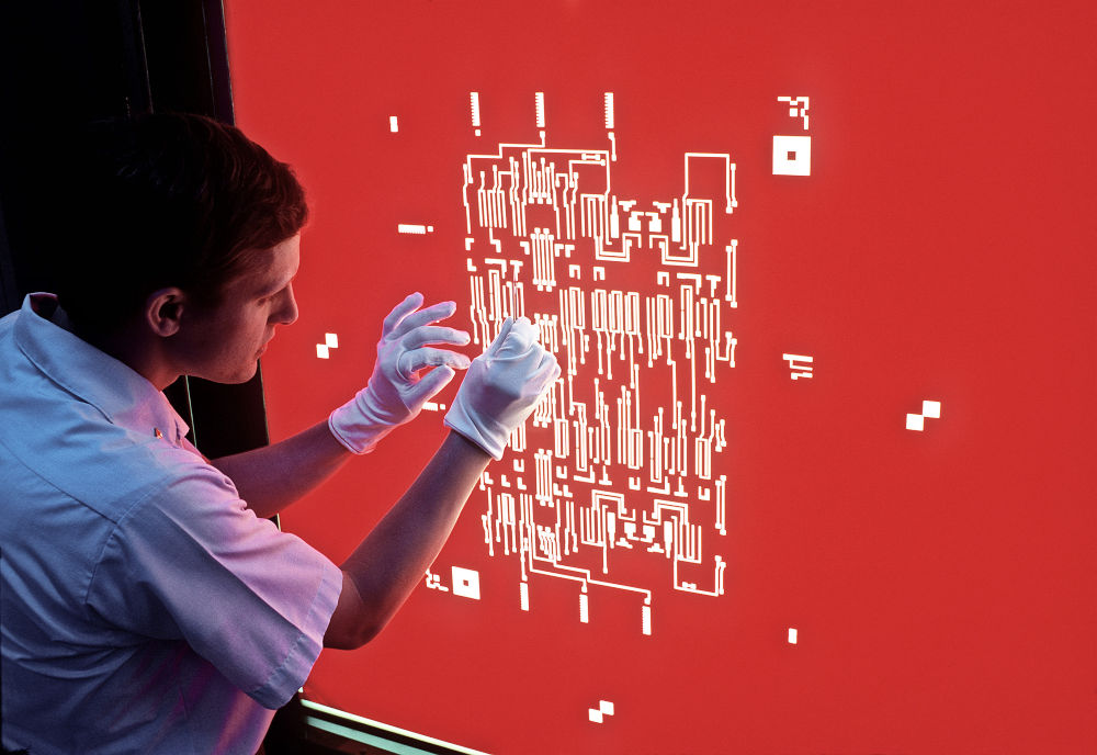
The first phase in the conversion from manual to automated mask making was to digitize the hand-drawn masks and then use the digitized files to drive a photoplotter, which would write the digitized patterns directly on photographic film.
Calma
The first company to offer such a system was Calma, which was founded in 1964 by Ron Cone, Calvin and Irma Louise Hefte, and Jim Lambert. Calma’s first product was a large flatbed digitizer that could digitize data from drawings or other sheet material. These digitizers were used in multiple applications from mapmaking to printed-circuit board and integrated circuit manufacturing. The Calma digitizer used a restrained cursor, which was held against the digitizing surface with X and Y cables. Because the X and Y axes could be locked independently, Calma digitizers were particularly applicable to digitizing printed circuit and semiconductor designs because they easily drew horizontal and vertical straight lines. These digitizers would output the digitized coordinates to punched cards or magnetic tape for storage.
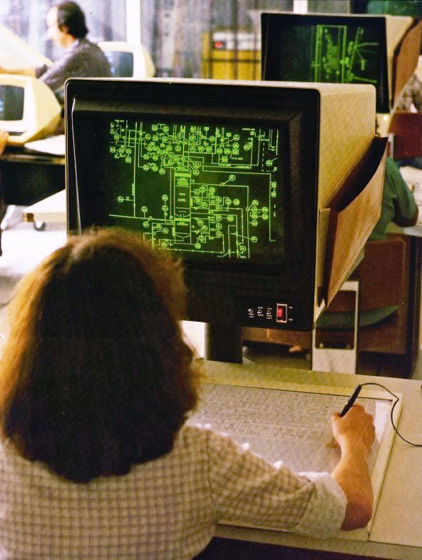
Initially, Calma digitizers were based on proprietary electronics using hardwired logic. (It was too early for microprocessors.) Calma then developed a new controller for the digitizer based on the 16-bit Data General Nova 1200 minicomputer. As with the earlier hardwired digitizers, the computerized digitizer would output data to punched cards or magnetic tape. High-end units stored data on hard disks. Then, in mid-1969, Calma hired Joe Sukonick, who developed additional software for the Nova 1200 minicomputer that transformed the digitizer into an interactive graphic system. The system he developed appeared in 1971 and was called the Graphic Data Station or GDS. Like most systems of the day, Calma’s GDS added graphical interactivity by using a Tektronix storage tube display.
In a recent comment to a LinkedIn post about the early days of chip design, Dan Clein, Chief Strategy Officer at LeadIC Design Canada and author of the book “CMOS IC Layout: Concepts, Methodologies, and Tools,” reminisced about his days at Motorola Semiconductor back in 1984 when Calma CAD systems were used for IC design. Back then, Clein used colored pencils, translucent plastic Mylar sheets, and Calma digitizing systems to develop the various IC mask layers. He used red pencils for the polysilicon FET gate layer, yellow for the diffusion mask layer, green for the P+ ion implant layer, purple for n-well diffusions, blue for the single metal mask layer, and black for contact cuts. Except for purple, these are the same colors described on page 64 and used to illustrate IC layers on the color plate images in the groundbreaking Mead-Conway book “Introduction to VLSI Systems.”
Clein worked on a large, backlit light table using a triangular rule with three different scales that made feature scaling easier. The drafting scale was 1000x, so one millimeter on the drawing represented one micron on the final IC mask. It was a completely manual design process, so there were plenty of mistakes and redrawn lines. Clein used a rechargeable electric eraser to help fix mistakes and make ECO changes. When the drawings were finished and checked, each Mylar sheet was digitized by hand with a Calma system.
(Author’s note: I used the same design techniques to define mask layers for circuit boards at Hewlett-Packard in the mid-1970s.)
Calma grew steadily through the 1970s and was acquired by United Telecommunications in 1978. (These days, United Telecommunications is known as Sprint, the wireless telephone carrier.) Just 30 months later, General Electric (GE) bought Calma from United Telecommunications. GE focused Calma on CAD systems for mechanical engineers, and the company’s electronics business started to slip. The 1980s would see the rise of next-generation CAE (computer aided engineering systems) from Daisy, Mentor Graphics, and Valid Logic. Calma didn’t make the transition from CAD to CAE and lost its momentum in the electronics arena. In 1988, GE sold Calma’s electronics business to Valid Logic.
Although the company was sold and its products faded from the market, Calma never really disappeared from the electronics scene. The data format of the original GDS system and that of its successor, GDS II, introduced in 1978, lives on and remains the standard database format used by the IC industry to define IC mask set layers. GDS II files are one of the bedrock interchange standards upon which the entire IC EDA industry is based.
Applicon
Applicon was the next of the big three CAD companies to be founded. A group of programmers – Gary Hornbuckle, Fontaine Richardson, Richard Spann, and Harry Lee – were working on advanced interactive graphics at MIT’s Lincoln Laboratory, and they decided the technology would make a fine foundation for a new company. Initially, they named their company Analytics, Inc. However, the name “Analytics” was taken, so the founders invented the new name: Applicon.
Part of the work done at Lincoln Labs was the development of command gestures entered on a tablet with a stylus. This form of command entry became one of the defining characteristics of Applicon’s products. GE was an early investor and eventually owned 28% of the company. Initially, the company targeted printed-circuit boards and integrated circuit designs. Early systems were based on IBM’s 1130 computer and used interactive terminals with a storage-tube display, keyboard and tablet from an MIT spinoff named Computek. Applicon selected the IBM 1130 computer because it could be leased, and Applicon thought that avoiding the initial hardware purchase would help in some sales situations. However, Applicon switched to the Digital Equipment Corporation (DEC) PDP-11 minicomputer after selling only a handful of the IBM-based systems. The company stuck with DEC for decades.
Unlike Calma and Computervision, which focused on selling systems to corporate drafting departments, Applicon focused on design departments in R&D labs. In another departure from its competitors, Applicon offered a mix of Tektronix storage-tube displays and raster displays based on Applicon’s own high-performance, 32-bit graphics processor based on bit-slice technology, which handled graphic tasks independently of the system’s central processor. By 1981, more than 90% of the company’s terminal shipments were raster devices. Applicon also designed and manufactured its own large-format, ink-jet color plotter in 1977. The plotter was not an on-line device. It was fed by a magnetic tape drive.
By 1980, Applicon had developed mechanical CAD software such as solids modeling packages. The company’s strongest market was still electronic design, but the greatest potential for future sales appeared to be mechanical CAD systems, and Applicon focused its software development accordingly. Applicon went public on July 22, 1980. Prior to Applicon’s public offering, General Electric offered to buy the remaining 72% of the company that it did not own, but the offer was rejected. GE then went shopping for another CAD/CAM vendor and acquired Calma. Just 14 months later, Schlumberger acquired Applicon in an all-stock transaction. Then, in 1985, Schlumberger merged Applicon with MDSI, which specialized in numerical control software. At the same time, Schlumberger split off Applicon’s electronics business and assigned it to another entity within the Schlumberger corporate structure named Factron, which made electronic test equipment. As a result, Applicon’s electronics business withered.
Schlumberger reversed this decision in 1986, but the damage had been done. Electronic design applications had gone from the company’s main product offering to around 10% of sales. Applicon was now basically a mechanical CAD company. By 1993, Schlumberger seems to have tired of Applicon and sold it to Alec Gores, the CEO of a private equity group called Gores Enterprises (now called the Gores Group), which specialized in acquiring technology-related companies that were subsidiaries of larger companies, paring down the staff and overhead expenses, and focusing on sales to existing customers. By 1999, Gore sold what was left of Applicon to Unigraphics Solutions. At that point, Applicon’s revenue came primarily from software maintenance.
Computervision
Philippe Villers escaped Nazi-occupied France in the 1940s and came to the United States through Canada. After earning an undergraduate degree from Harvard and an MSME degree from MIT, he spent a few years in GE’s management training program. He then worked for Perkin Elmer, Barnes Engineering, the Link Division of Singer-General Precision, and Concord Control in Boston. In 1969, Villers founded Computervision with Martin Allen, who had been Villers’s boss at Singer. Allen had worked for TRW and Martin-Marietta in addition to Singer.
Villers and Allen planned to enter the CAD market, aiming specifically at the electronics market, but the company needed immediate income while the CAD products were being developed, so Villers designed an automatic mask aligner to sell to the semiconductor industry. He purchased manual mask aligners from Kulicke & Soffa, an early entrant in the nascent semiconductor equipment industry, and added mechanical drive mechanisms and control electronics to convert the aligners to automated use. Computervision’s Autolign quickly became a best seller for the company and was a significant revenue source for several years.
The company aimed its first CAD product, named CADDS-1 (Computervison Automated Design and Drafting System), at the printed circuit and general 2D drafting markets. CADDS-2 added capabilities for IC design. Although the company’s original intent was to base its CAD systems on computer timeshare systems, the 300-baud telecommunications systems of the day would simply not support interactive design. CADDS-1 and -2 ran on 16-bit Data General Nova 1200 minicomputers and used a 16-bit database for designs, which quickly reached its limits.
Like most CAD systems of this era, the CADDS systems used Tektronix storage-tube displays. CADDS-2/VLSI, introduced in the late 1970s, was based on a 32-bit database running on Computervision’s CGP-100 graphics data processor, which was heavily based on Data General’s Nova architecture but with expanded memory addressing and additional graphics instructions. Data General was not thrilled by having Computervision bootleg its minicomputer architecture.
CADDS-3 focused on 3D mechanical design, and the company started to lose interest in the electronics markets. Villers left the company in January 1981 after two of his new venture proposals were rejected. One of those proposals was for a low-cost system that combined the computer and terminal into a single integrated system. Today, we call those systems engineering workstations, and they would become a huge business in the 1980s. Villers’ other proposal had been to take Computervision into the robotics and artificial vision markets. After he left Computervision, Villers founded a company named Automatix, which entered those two markets.
Eventually, Computervision would adopt Sun workstations and end its computer manufacturing efforts. By the late 1980s, Computervision was firmly focused on mechanical and AEC (architectural, engineering, and civil or construction) markets. Prime Computer acquired Computervision in 1988, but the company had ceased to be a force in the electronics market years before.
Instead, three new companies were forging ahead. These were not CAD companies because the electronics industry now needed more design support than computer-aided drafting could provide. The industry needed a productivity boost from CAE (computer-aided engineering) systems, which were tailored to the needs of electronic engineers who were beginning to develop complex multi-layer circuit boards, custom ICs, and gate arrays. The 1980s saw the rise of three new companies to lead this exploding new market, which I’ll discuss in Part 3 of this series.
References
David E. Weisberg, The Engineering Design Revolution, 2008
Carver Mead and Lynn Conway, “Introduction to VLSI Systems,” Addison-Wesley, 1979
Acknowledgement
This article would have been impossible without the meticulous research in David E Weisberg’s 667-page book, The Engineering Design Revolution. Weisberg passed away in 2018, but his book has been reproduced here. Weisberg’s book is encyclopedic and contains entries for many CAD companies including Auto-trol, where I worked from 1980-1982.
Dedication
I dedicate this article to my first mentor, Robert Bauer, who spent three years teaching me drafting skills in high school. Everyone should have the privilege of learning from a mentor like Bob Bauer.


Steve,
I’m enjoying your history of the EDA industry, but have a few comments to add regarding Calma. A bit of my personal EDA history: In 1981, I was at the GE Corporate R&D (CR&D) Labs in Schenectady, when Calma became one of the components of the company’s (brief) strategy to rebuild a presence in microelectronics. That lasted until Jack Welch came in and directed the company would only own businesses that were #1 or #2 in their industries, which clearly wasn’t going to happen in semiconductors. GE had bigger plans for Calma, but that didn’t mean they entirely shifted the focus to mechanical EDA.
In 1981, I had just left TI the previous year, after completing my MSEE at Southern Methodist University, where Ron Rohrer had been Department Chair, and Aart DeGeus was completing his PhD. Coincidentally, all three of us went from SMU to different parts of GE: after I went to the Labs, Ron left SMU to go to Calma, and Aart started working at the GE Microelectronics Center (MEC) in Research Triangle Park.
At CR&D, we were developing a 1-micron CMOS process, and working on developing a design methodology to enable non-IC designers in other GE divisions to create their own chips, using a “macrocell” library of analog, mixed-signal, and digital blocks. We collaborated with MEC and Calma, especially when it came time to bid on a project for the VHSIC program.
In 1984, I left CR&D to productize our work at GE-Datel. We continued to use Calma workstations until I left there in 1988. Although there were many factors that led to Calma’s demise in the IC industry, I believe the most significant was the emergence of Cadence and it’s design framework, not its ownership by GE. You mentioned Daisy, Mentor, and Valid (the old DMV to industry vets like us), but for custom IC design – it was the ability to run DFI (where I started) and then DFII on a Sun Workstation that completely transformed the industry. When I was tasked with creating an IC-design capability at MicroNetworks, that was the system I installed. Now, I could do schematic entry, simulation, and layout, all in a single integrated environment.
Mike, thanks for writing about your personal experiences. Jack Welch became GE’s Chairman and CEO in 1981 and GE’s semiconductor businesses seem to have wound down swiftly after that. I’ve no doubt that it took years to run out Calma’s leadership, but I’ve seen no evidence that Calma was a driving force in the electronics industry after Neutron Jack’s reign started. This article (Part 2) mentions Daisy, Mentor, and Valid. The next article (Part 3) is devoted to the stories of those three companies.
So, I have a funny story of the time Welch brought the BoD to tour the labs. My team had setup a demo in the Calma room, but because the PR folks thought it would be undignified for them to bend over to see our screens, we propped each one of them up on wooden blocks. And wouldn’t you know it.. Jack comes over to my station, and proceeds to sit on the benchtop.. swinging his legs!!! I didn’t think I should dare ask him to get down… but then the demo froze. I was freaking out, but demonstrating the great political skills that all GE execs were trained to have.. the head of the labs just swooped in and made up some story about what had happened.. and off they went to the next demo.
But back to Calma the company.. they failed in their attempts to port their software to the new Apollo and Sun workstations, but until the late 80s, they were still the most popular IC layout platform. Had nothing to do with GE.
Indeed, a funny story. I’d have to ask you to cite references to Calma’s being the “most popular IC layout platform” in the 1980s. If you’re referring to custom IC layout, especially analog, especially at Datel where you worked (I used Datel parts as a design engineer), then sure. If you’re talking about IC layout based on the Mead-Conway design methodology, then Daisy, Mentor, and Valid quickly left Calma in the dust. There’s no mention of Calma making that transition in the literature I have researched.