

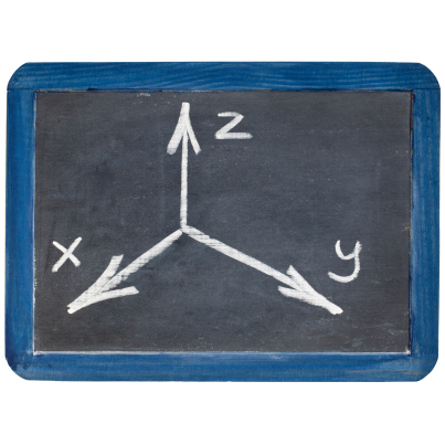
3D is one of the hottest buzzwords these days. Every marketeer worth his salt is trying to find a way for the next “new thing” to be plausibly labeled as “3D.” 3D is cool. We see it in movies. The bad guys jump right out from the screen. 3D is real, vibrant, and immersive. 2D is, well, flat and boring.
When Tabula introduced their time-multiplexed FPGA fabric a few years ago, they proudly raised the 3D flag. Ahem, OK, so their chips aren’t EXACTLY 3D. Not in the physical sense. But, if you imagine the routing resources in a 3D projection of the 2D surface where each time step of the multiplexer reaches a different plane in the Z axis, you can plausibly… Well, you can plausibly say that “3D” was a marketing spin. Tabula’s chips are cool and innovative, but not really 3D.
When Xilinx parked four planar FPGA slices side-by-side on a silicon interposer, they whispered the 3-word, but then backed off to “2.5 D” and really turned down the dimmer on that term in favor of “SSI” for “Stacked Silicon Interconnect”. While Xilinx’s Virtex-7 2000T product is groundbreaking, it is not the mythological “3D” device that we’ve all been waiting for. It does, however, hint (but not deliver) on one of the most intriguing promises of 3D IC technology – heterogeneous devices.
Intel was quite forthcoming with the 3D-ness of the “not a FinFET” Tri-gate transistor technology in their 22nm CMOS process. Intel’s 3D Tri-gate process creates a non-planar transistor by stacking a gate on top of two vertical gates to increase effective area by a factor of three. While this does dramatically reduce leakage current and improve power consumption, it is not the mythical “3D IC.”
Before we get too far in defining 3D ICs, we might want to visit the fundamental question: “Why do we want 3D ICs in the first place?” Of course, “because they’re cool” is not a valid reason to go dumping billions of dollars into development. We need some tangible benefits to expect before we go tackling TSVs and microbumps.
As we know, there are practical limits to the physical size we can make a planar IC. As our devices get larger, the probability of defects increases exponentially. Building a larger chip out of smaller chips can help to address that yield limit. By stacking smaller die (whether side-by-side or one atop another) we could build almost arbitrarily large devices without bumping into size limits.
Also, as our planar designs get larger, the problem of placing and routing them near-optimally gets more difficult. The distance across a large chip can create congestion, making routing a nightmare. Placement and routing in three dimensions instead of two can help to alleviate the congestion and distance issues.
Finally, process technology is always a compromise. The best semiconductor process formula for making a processor is different from memory, which is much different from analog. With monolithic, planar ICs, we are forced to choose a compromise process technology that works for everything but isn’t optimized for anything. With heterogeneous 3D ICs, we have the possibility to fabricate each part of our device with the technology that is best for that purpose.
We recently chatted with Altera’s Brad Howe – Senior VP of R&D – about Altera’s efforts in 3D FPGA development. While Xilinx’s initial 3D efforts focused on yield improvement, creating a larger effective die by stitching together several smaller ones, Altera’s focus has been on heterogeneous devices – using an interposer to stitch together die that were fabricated with different processes. Howe pointed out that the changing role of FPGAs in the system – from glue logic to the central piece of silicon in many systems – is driving FPGAs to become SoCs in the true sense of the word, incorporating processors, peripherals, memory, analog, and other system elements in a single package. To reach those goals in the long run, 3D IC technology will almost certainly be required.
So – if our 3D ICs are really franken-chips made from multiple dies stitched together, how is that different from just putting several ICs on a board? The answer is: pins and power. In order to move a signal from one chip to another on a board, we have to push enough power to drive the signal through a relatively long PCB trace to the next chip. That means that our external IO drivers on each chip have to be big, and they need bonding pads so we can hook up to them from the outside world with our big clumsy bonding wires and solder balls. Those big IOs and pads become limiting factors in IC design, and they severely restrict the number of signals we can connect between our various chip-lets.
3D ICs are, therefore, really mostly about packaging technology. By using a silicon interposer, TSVs, or other micro-connections between chips, we can use much smaller IOs and can move many times more signals between chips. More signals and lower total power consumption are great things. Ultimately, being able to make more of our connections inside our SoC package means we may not need as many connections outside the package, giving us even more benefit.
The challenges are formidable, however. Many companies have been vocal recently about 3D (or 2.5D) technologies not being ready for prime time. Xilinx has perhaps been the most visible example of moving the technology into production, but their case can hardly be considered “volume production,” as the big ‘ol V2000T will sell in miniscule quantities to a handful of folks who can dish out the really-big bucks for the largest FPGA on the market. In order for 3D technologies to make it into the sockets of the average system, some serious obstacles need to be overcome.
One of the toughest issues for future 3D ICs is power – or more specifically, heat. When you stack all those dies one on top of another, there is nowhere good for the heat to go. The ratio of things generating heat to surface area goes in the wrong direction – dramatically. Heat piles up and has no escape. Add to that the fact that all these different chips dissipating different amounts of heat expand and contract at different rates. That means that trying to keep thousands of tiny connections aligned and connected can be challenging. Finally, all the additional complexity of assembly adds to the cost and the failure potential of 3D devices.
There is more than just technical complexity slowing down the 3D IC movement. 3D technology will ultimately require collaboration between dozens of suppliers in different domains and some forms of standards that haven’t even been started yet. If you want to build an arbitrary system on top of a silicon interposer, you’ll need the supplier of each slice to be intimately involved in the specification of the interconnect. The memory slices will need to connect nicely to the processing subsystem, which will need to be easily accessible by the programmable logic fabric. That level of cooperation isn’t evident yet in the industry, as the publicized 3D efforts so far have each been more centrally controlled by one company. Building out the ecosystem for 3D may, in fact, end up being the biggest challenge of all.
Someday, however, we may not think about FPGAs anymore. We may be buying complex multiply-programmable SoC devices that include FPGA fabric as one of several programmable components. These devices will contain processing subsystems, memory, interfaces, and analog, as well as a host of specialized peripherals. They will most likely be packaged with advanced techniques that incorporate multiple chips in a single package – whether we call that “3D” or not.


When will we have real 3D FPGAs? Why do we even want 3D FPGAs? What do you think?