editor's blog
Subscribe Now

Old-School Analog Outputs

Today we looked at the role of Freescale’s new FXLN83xxQ accelerometer for analyzing vibrations. But one feature of the accelerometer had me cocking an eyebrow: analog outputs.

We’ve covered a lot about sensors here before, and in the huge majority of the cases, a sensor consists of a MEMS (or other) sensing element, an ASIC to clean up and digitize the signal, and then a series of registers where all the relevant data gets placed.

An outside entity, like a sensor hub, can then read those registers over a bus connection – typically I2C or SPI. What could be simpler?

Well, I guess an analog output could be simpler: you eliminate all of that messy digital stuff. But it seems to me that, running an analog signal halfway across town to get it to the analog inputs of a microcontroller (aka MCU, or whatever hub is used) would run the risk of seriously degrading the analog value in a way that wouldn’t happen with a digital signal.

XL_schematic_red.jpg


(Click to enlarge)

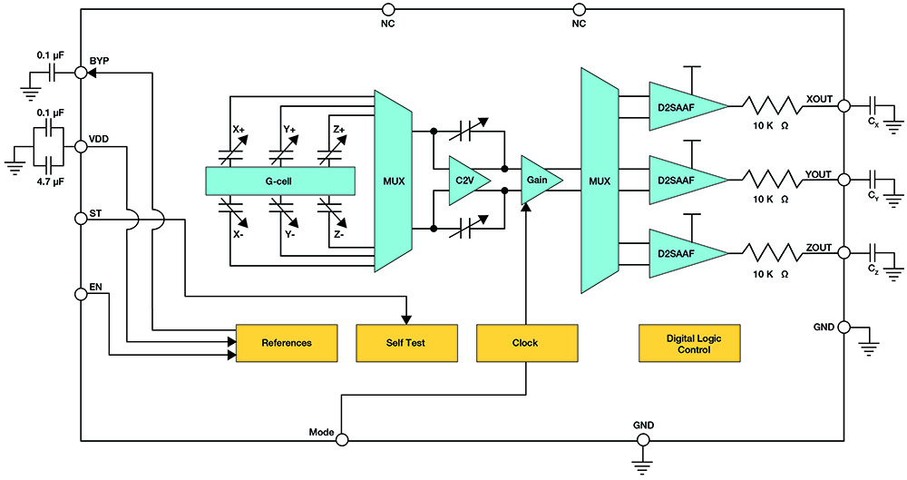
Image courtesy Freescale.

I asked Freescale about this, and they justify it based on the wide variety of digital interfaces in use, in particular in industrial settings. Heck, they say that even CAN bus is leaving the confines of vehicles and moving into other applications.

Freescale makes lots of microcontrollers. This variety of MCUs partly reflects the diversity of interfaces they may talk to: Rather than having one large unit with all possible interfaces, they offer different devices. And yes, they’re assuming (or at least hoping) that you’ll be using their MCU.

So the idea goes thusly: first off, you simply don’t run the analog signals halfway across town. In these applications, an MCU is likely to be right nearby. (If not, then you want to move it so that it is nearby.) The MCU you choose will then reflect whatever bus you’re using, and that’s where you go digital. They prefer this, obviously, to having to have a bunch of different versions of the sensor to suit the various digital protocols.

There’s one other convenient thing about digital registers, however: they’re good at storing values while the rest of the system goes to sleep for a while to reduce power. Well, apparently these analog outputs can manage the same trick. The internal electronics shut down between samples, but the output is held between samples. This decouples the rate at which the MCU samples the analog outputs from the rate at which the sensor samples the system and allows power as low as 200 µA when running.

That’s how they see it; if you see it differently, then your comments are encouraged below.

Leave a Reply

featured blogs
Apr 25, 2024
Structures in Allegro X layout editors let you create reusable building blocks for your PCBs, saving you time and ensuring consistency. What are Structures? Structures are pre-defined groups of design objects, such as vias, connecting lines (clines), and shapes. You can combi...
Apr 25, 2024
See how the UCIe protocol creates multi-die chips by connecting chiplets from different vendors and nodes, and learn about the role of IP and specifications.The post Want to Mix and Match Dies in a Single Package? UCIe Can Get You There appeared first on Chip Design....
Apr 18, 2024
Are you ready for a revolution in robotic technology (as opposed to a robotic revolution, of course)?...

featured video

MaxLinear Integrates Analog & Digital Design in One Chip with Cadence 3D Solvers

Sponsored by Cadence Design Systems

MaxLinear has the unique capability of integrating analog and digital design on the same chip. Because of this, the team developed some interesting technology in the communication space. In the optical infrastructure domain, they created the first fully integrated 5nm CMOS PAM4 DSP. All their products solve critical communication and high-frequency analysis challenges.

Learn more about how MaxLinear is using Cadence’s Clarity 3D Solver and EMX Planar 3D Solver in their design process.

featured paper

Designing Robust 5G Power Amplifiers for the Real World

Sponsored by Keysight

Simulating 5G power amplifier (PA) designs at the component and system levels with authentic modulation and high-fidelity behavioral models increases predictability, lowers risk, and shrinks schedules. Simulation software enables multi-technology layout and multi-domain analysis, evaluating the impacts of 5G PA design choices while delivering accurate results in a single virtual workspace. This application note delves into how authentic modulation enhances predictability and performance in 5G millimeter-wave systems.

Download now to revolutionize your design process.

featured chalk talk

FleClear: TDK’s Transparent Conductive Ag Film
Sponsored by Mouser Electronics and TDK
In this episode of Chalk Talk, Amelia Dalton and Chris Burket from TDK investigate the what, where, and how of TDK’s transparent conductive Ag film called FleClear. They examine the benefits that FleClear brings to the table when it comes to transparency, surface resistance and haze. They also chat about how FleClear compares to other similar solutions on the market today and how you can utilize FleClear in your next design.
Feb 7, 2024
10,966 views