


For reasons that will be revealed in the fullness of time, I’m wrestling with a passel of perplexing posers revolving around the math associated with a torus (plural tori), which is colloquially known as a donut.
Before we plunge into the fray with gusto and abandon, let’s first remind ourselves that, in the realm of mathematics, the topical topic of topology is concerned with the properties of a geometric object that are preserved under continuous deformations, such as stretching, twisting, crumpling, and bending; that is, without closing holes, opening holes, tearing, gluing, or having the object pass through itself.
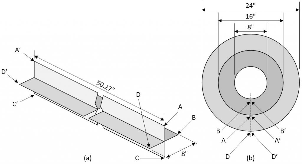
In my case, it’s the twisting trait of topology that’s currently causing my poor old cranial matter to spin like a top. As a starting point, I want you to imagine a giant donut whose outer diameter is 24” and whose hole in the center has a diameter of 8” — something like the handy-dandy image shown below.
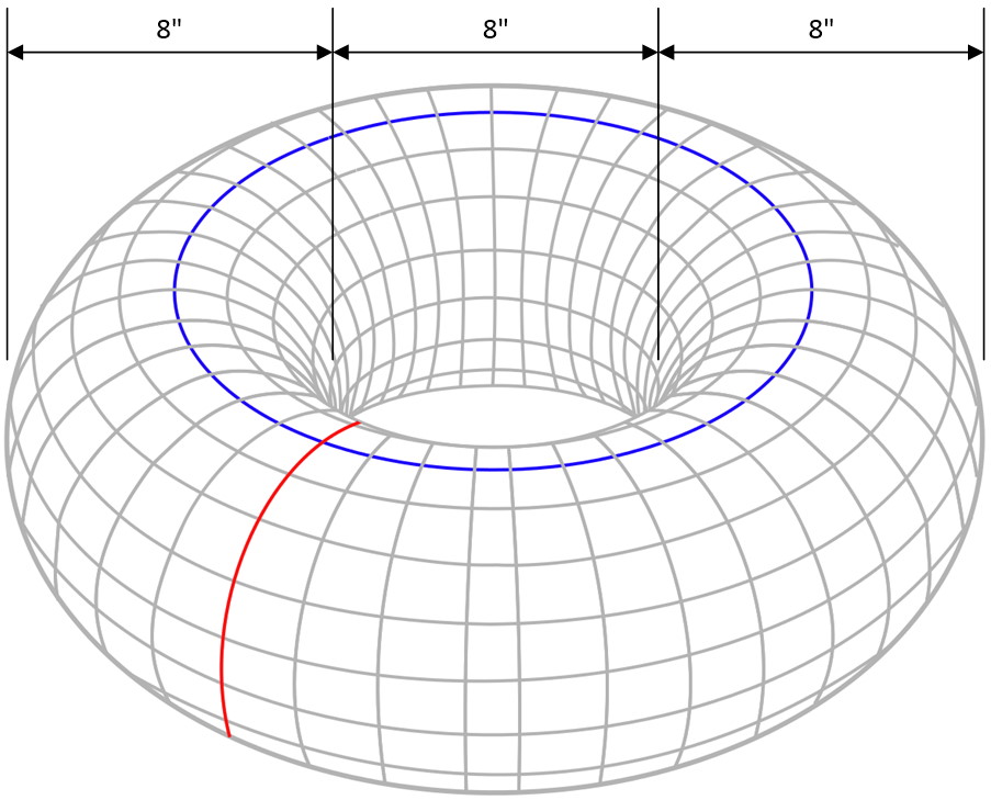
I don’t care what you say, that’s one big donut (Image source: Wikipedia/Max)
Now, suppose we cut a strip of paper that’s 8” wide and 50.27” long as shown in (a) in the illustration below. Why 50.27” long? Well, if we wrap this around to make the ends meet to form a cylinder, then the diameter of this cylinder will be 16”, which is half-way between the outer diameter of my donut and the inner diameter of its hole as shown in (b) in the illustration below.
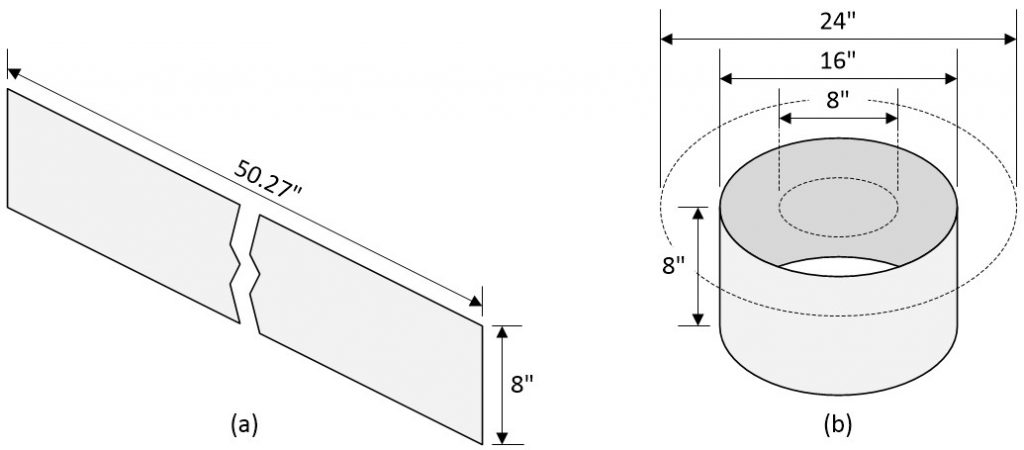
Forming a cylinder from a single strip of paper (Image source: Max Maxfield)
The reason for creating this cylinder with a diameter of 16” will become apparent in the fullness of time. First, however, observe that the cylinder in the image above has two edges (top and bottom) and two faces or surfaces (inside and outside). If we put a finger at some point on either of the edges and move it around the cylinder until we return to our starting point, we will — not surprisingly — have gone around the circle a single time, and similarly for either of the faces.
Now, I’m sure we’re all familiar with the concept of a Möbius strip (a.k.a Möbius band a.k.a. Möbius loop). The idea here is that we start out with our original strip of paper, wrap it around so one end meets the other, but then give one end a half-twist by rotating it through 180° before joining the ends together as illustrated below.
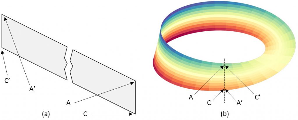
Creating a Möbius strip (Image source: Wikipedia/OgreBot/Max)
The result has only a single edge and a single face. If we were to place a finger at some point on the edge and move it along the edge until we return to our starting point, we will have essentially “gone around the circle” two times, and similarly for the face.
One final point to note is that, if we were to give one end a full twist by rotating it through 360° before joining the ends together, then we would return to having two surfaces and two edges. Another way to represent all three cases we’ve discussed thus far would be as illustrated below.
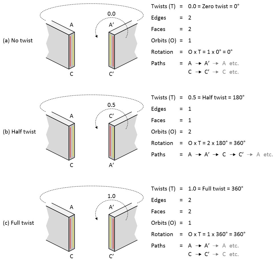
Recapping the first three examples using an alternative depiction
(Image source: Max Maxfield)
In this case, the term “orbits” refers to the number of times we have to go around the strip before returning to our starting point. Also, observe the red and yellow lines. Make sure you understand why the lines between A’ and C are presented as they are for (a) and (c); also, why they change for (b). These lines will prove useful for working out what’s what as we dive deeper into the morass and face the horrors that are to come.
Now, you may be thinking that this is all a tad trivial. If so, how about we up the ante? Remember that our original strip of paper was 8” tall. Suppose we form a “cross-strip” by attaching two additional strips to the center of the original strip, one on each side mounted at 90° as shown in (a) below. In this case, the corners of the cross-strip are labeled A, B, C, and D at one end and A’, B’, C’ and D’ at the other end. Let’s assume that each of these new strips is 4” wide, meaning that the two combined are 8” across.
Upping the ante (Image source: Max Maxfield)
In the case of this basic cross-strip, prior to us performing any twisting and connecting, we can say that it has four edges: A to A’, B to B’, C to C’, and D to D’. We can also say that it has four faces: both sides of the plane bounded by A to A’ to C’ to C, and both sides of the plane bounded by B to B’ to D’ to D.
Now suppose that we take one end of the cross-strip, bend it around without twisting it, and connect it to the other end such that A connects to A’, B connects to B’, C connects to C’, and D connects to D’.
A top-down (bird’s eye) view of our “donut” is as shown in (b) above. Remember that our cross-strip still starts out as being 50.27” long, resulting in the diameter of the A to A’ circle being 16”. If we assume that our new “side strips” are created out of a special type of paper that stretches or compresses as required, then the outer diameter of our donut will be 24” and the diameter of the hole in the center will be 8”, thereby matching the size of our original donut.
Suppose we place a finger at point D and slide it clockwise around the outer edge of our donut until we reach point D’. Not surprisingly, we will have gone one time round the circle and the distance travelled will be the circumference of this circle given by 2*Pi*r = Pi*D = Pi*24 = 75.40”.
OK, now suppose that we create two new instantiations of our cross-strip donut, one with a half-twist and one with a full twist. We can summarize our three cross-strip incarnations as illustrated below.
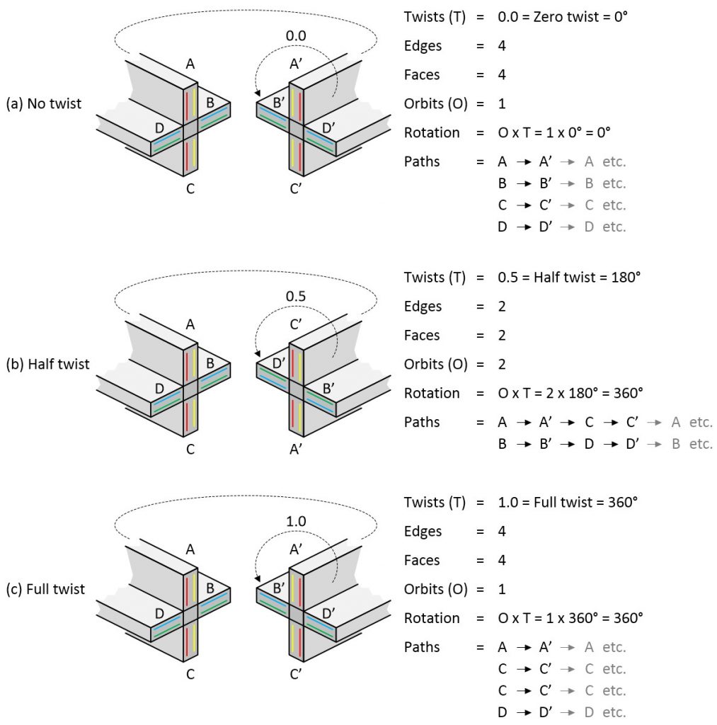
Summarizing our three cross-strip incarnations (Image source: Max Maxfield)
I fear that you may still be thinking that this is all “easy peasy lemon squeezy,” so let’s bump things up just one more notch. Suppose that, just before connecting the ends of the cross-strip, we apply a quarter-twist to one of the ends by rotating it through 90° before joining the ends together as shown below.
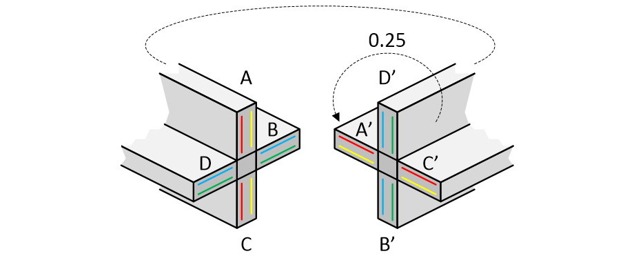
Giving our cross-strip a single quarter twist (Image source: Max Maxfield)
So, in this quarter-twist case, how many edges do we have? How many faces do we have? And, if we place our finger at point A, how many times will we go around the circle before we return to our starting point (I bet you’re glad I added those colored lines now LOL)?
As a bonus question, remembering that our finger is going to be following a spiral path that will take it between the outside (24” diameter) and inside (8” diameter) of our donut, how far will it have travelled?
I was going to expound, explicate, and elucidate further, but I don’t think it’s fair for me to have all the fun (I’ve been dreaming about this stuff for the past few nights), so I’ll leave you to noodle for a while, and we will revisit this conundrum in a future column. Until then, as always, I welcome your comments, questions, and suggestions.


My friend Peter Traneus Anderson (a.k.a. Traneus Rex) correctly answered my poser as follows:
Twists = 0.25
Edges = 1
Faces = 1
Orbits = 4
Peter then went on to pose a conundrum of his own as follows:
For zero radians twist per rotation around the donut, we have your 0-degree case.
For pi radians twist per rotation, we have your 180-degree case.
For pi/2 radians twist per rotation, we have your 90-degree case.
For one radian twist per rotation, we have …?