

Get ready to geek out.
I’m a big fan of math. I know… hardly a bold coming-out statement. But I’m also sometimes not a fan. In school, I found that there was sometimes too much blind adherence to math. When you asked why something happened, they’d say, “Because the equations say it happens.” Which isn’t really true: math is supposed to be a model of the truth; it’s not the truth itself. Something physical happening can be modeled by math, but when I ask why something happens, I want to understand the physical mechanism – that’s what makes something happen. The math comes after.
That said, sometimes the math leads us to surprising conclusions that we would never have thought of if we considered only the physical mechanisms – especially since our understanding of the physical may be flawed or incomplete. In fact, equations to model a physical theory can end up helping us to refine the physical theory. Sometimes what seem like weirdnesses in the equations reveal a mistake or limitations in the mathematical model; other times they point to interesting times ahead. You have to test them to figure out which is which.
All of this leads us to one such surprising result: negative capacitance. We understand – both mathematically and physically – how your everyday run-of-the-mill capacitance works: applied electric fields across a gap attract charges. There’s no way that would explain negative capacitance, which suggests that… what… the positive side of an electric field attracts holes in a semiconductor? That makes no sense.
But certain equations say it’s so in certain circumstances, and some practical results have been recently demonstrated. Both the background and a results paper were presented at last fall’s IEDM conference, and we’re going to review the notion here. The first paper, by Asif Islam Khan of Georgia Tech, lays out the basics of why this happens. It’s been known (or at least expected/suspected) since a “Landauer paper” in 1957, but the purpose of the Khan piece was to provide a “microscopic-level” explanation that had been missing.
The second paper involved a wide-ranging team from National Applied Research Laboratories, National Taiwan Normal University, and National Chiao Tung University, all in Taiwan, as well as UC Berkeley. One participant was Chenming Hu, widely considered the father of the finFET. This team reported on the effects of negative capacitance on finFETs and other circuits having ferroelectric gates.
The critical thing from the second paper that we’re going to look at is the so-called subthreshold swing (SS). This basically says how quickly a transistor can turn on, and, to date, all efforts have been focused on getting that SS as close as possible to the theoretical “Boltzmann” limit of 60 mV/decade. Negative capacitance suggests you can beat that limit. Or, said more cautiously, the equations say you can; does that bear out in reality?
We’ll look first at the basis for negative capacitance, and then we’ll look at its effect on SS and how that second team did.
How Could Capacitance Be Negative??
OK, we’re going to do some math, folks, focusing on ferroelectric materials. I usually avoid that, preferring to focus on intuitive aspects of phenomena that give life to the otherwise soulless equations. But today we’re all about the math. I’m not going to go into excruciating detail on this; I’ll cherry-pick, and you can review the original paper for the gory details. (In fact, the author doesn’t even derive everything, referring to other papers for pieces of it.)
The first thing we need to look at is the so-called Curie temperature. Originally conceived as a temperature above which permanent magnets lose their fixed magnetic state, it also features in a relation describing how an applied field E relates to polarization. The equation is a polynomial, the first term of which involves the factor (T – TC), where TC is the Curie temp. The negative capacitance happens where this factor is negative – that is, below the Curie temperature.
Within that temperature range, there’s this positive feedback resulting in a negative slope on a curve of polarization vs. applied electric field, although there are a couple of limiting factors:
- The linearity of the negative slope is limited by saturation. They talk of stretching dipoles, but, just like any spring, there are limits to how far it can be stretched.
- This region is unstable. In the absence of an applied field, thermal noise, through this positive feedback, spontaneously polarizes the system into one of the normal stable states consistent with positive capacitance.
This characteristic is illustrated by a characteristic S-curve that was predicted by Landau, but is only now getting studied at the microscopic level using a “toy model.”
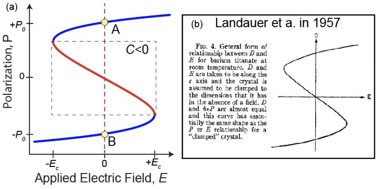
(Image courtesy IEDM; credit A. I. Khan)
Let’s dig into where this positive feedback comes from. And, while it may sound like me talking here, credit where due, this is Mr. Khan’s paper talking through me. And hoping I get it right. The dipole moment p of a dipole is a function of the local electric field, which is itself made up of the field it feels from other dipoles nearby and from an applied field. Skipping some steps, this leads to the relation:
![]()
where:
- α is what they call the linear polarizability; as we’ll see, it varies with temperature;
- ε0 is the vacuum permittivity;
- ζ is a structural factor related to how the dipoles are physically arranged; we’ll consider it a constant; and
- Eapp is the applied field.
What we think of as the dielectric constant εr relates the permittivity of a specific material ε to the vacuum permittivity:
![]()
From the first equation – again, skipping steps – Mr. Khan gets that:
![]()
Now, it turns out that α is inversely proportional to temperature and that, at the Curie temperature,
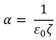
So, at CT, the dielectric constant gets a <horrors!> zero denominator – referred to as the polarization catastrophe. At lower temperatures, α gets larger, meaning that the denominator goes negative. And there’s yer negative capacitance. The equations never lie, right?
By the way, they illustrate the positive feedback loop through the following figure.
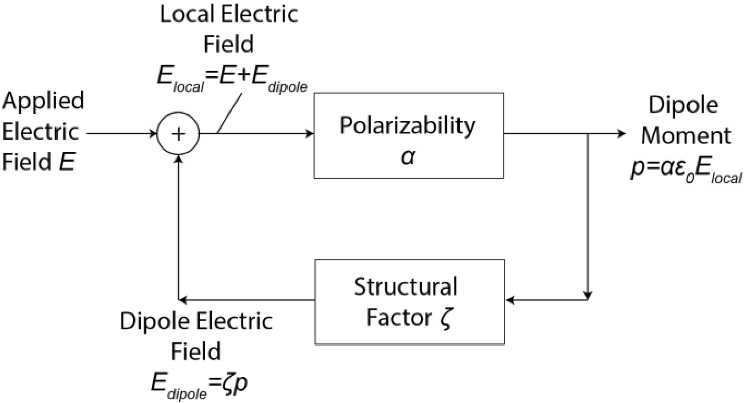
(Image courtesy IEDM; credit A. I. Khan)
Swing Low
OK, so, now that we’ve examined a theoretical view of the phenomenon, let’s get more practical by looking at what happens when we use a ferroelectric material as the gate oxide of a finFET. The SS is the inverse of the subthreshold slope (a FET’s IV curve below threshold), and it’s expressed as:
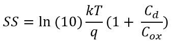
where:
- Cd is the capacitance of the depletion layer,
- Cox is the gate oxide capacitance, and
- kT/q is the same kT/q you’ve seen your whole career (Boltzmann’s constant; temp; charge of an electron)
Just as a higher subthreshold slope indicates a faster current response to changing voltage, a lower subthreshold swing (being the inverse) is what device engineers have been gunning for. When Cd is 0 or Cox is infinite, that right hand capacitance ratio disappears, and you’re left with
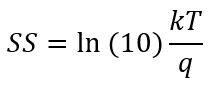
This is the thermionic, or Boltzmann, limit that gives 60 mV/decade, and we’ve been treating it as the best we can do, since any non-zero (positive) capacitance ratio makes it larger. But if Cox can be negative, then the SS can also become smaller than that limit. Or at least that’s what the equation suggests. What happens in practice when this second team works their magic?
The team used HfZrO2 (sometimes abbreviated as HZO) as the finFET gate dielectric. And, skipping over all their hard work and going straight to the chase, they achieved an SS of 5 mV/decade over four decades of drain current. This isn’t marginally less than 60; it’s way less than 60.
They satisfy themselves with reporting the results without hyping up the possible implications, but… it would seem like this would be pretty dang exciting. Makes you wonder when (if?) we might see a whole new generation of circuits using ferroelectric gates!
You can find way more than I’ve given you here in the papers listed below. (You’ll need the IEDM proceedings or a way through paywalls.)
More info:
“On the Microscopic Origin of Negative Capacitance in Ferroelectric Materials: A Toy Model,” A. I. Khan, IEDM 2018 paper 9.3
“Negative-Capacitance FinFET Inverter, Ring Oscillator, SRAM Cell, and Ft,” Kai-Shin Li et al, IEDM 2018 paper 31.7


Next they will be claiming atomic fusion at the junctions. Recall that ‘resistor’ hysteresis was first observed/reported ~1910, mathematically postulated in ~1970, and physically demonstrated ~2000. We are approaching THE ‘singularity’.