


A few weeks ago, we talked about software security, and a question was raised about the reliability of physically unclonable functions, or PUFs. We noted at the time that Intrinsic ID agreed that the issue exists, but that they had a solution that more than compensated. Today we take a look at the whole issue in more detail. Possibly too much detail. Put your wonk hat on, cuz we’re about to geek out!
PUF Basics
First, let’s look at some fundamental concepts surrounding PUFs, because it occurs to me that there are two kinds of randomness at play – one good, the other not so much.
As a reminder, a PUF is some physical characteristic of a silicon chip that can serve as a specific ID for that chip. If you’re new to PUFs, that might sound counterintuitive, since the whole idea of semiconductor fabrication is to make high volumes of identical chips. So what gives?
Well, there are many aspects of a chip that suffer from variation. So good designers are going to beef up their designs to compensate for – and neutralize – that variation. An example is transistor threshold voltage: we know that it will vary slightly – and randomly – from lot to lot and that, in more aggressive nodes, even from wafer to wafer or die to die. But, if you go with enough decimal points (and I don’t think it takes a lot), it can also vary from transistor to transistor.
Imagine that a power-up state relies on hundreds or thousands of such randomly distributed transistors. A prudent designer would most likely create some deterministic power-up circuit that will put this and any other circuits into a known, predictable state. From the standpoint of normal circuit operation, this randomness isn’t good and needs to be fixed.
The Good
An embedded SRAM is an example of a circuit that definitely has some power-up unpredictability, which is why you wouldn’t want to rely on the contents of that memory without ensuring that it has been written to or reset first. But an SRAM happens to be a circuit where this uncertainty can be a benefit if employed for the right reasons. When you power up your chip, what will the initial raw SRAM contents be?
This is the notion behind a common approach to a PUF. Each chip’s memory powers up in a slightly different state. If there’s enough randomness – security folks would dub it entropy – and if the SRAM is big enough to give a huge number of possible power-up states, then it’s supremely unlikely that two chips will power up into exactly the same state.
Normally not a good thing, this turns out to be rather nice for assigning an ID to a chip. If you’re trying to manage key security, for instance, this can provide you with a root key from which all other session keys and other so-called ephemeral keys can be derived – and derived in a way that makes it impossible to deduce the original key from the PUF. In PUFland, they refer to this natural power-up state as the enrolled state.
The Bad
So the randomness that makes this possible is, for our purposes, a good thing. But here’s some other randomness that isn’t: what happens if the SRAM doesn’t boot up the same way each time? In other words, what if the start-up state itself has some randomness associated with it? That is, in fact, the case, so many PUF approaches apply some error correction to ensure that the state is consistently read each time. The key here is that this particular flavor of randomness is limited enough that you can manage the spread in the start-up states and tame the uncertainty.
Now, we can muse deeply on what the causes of that start-up-state variation might be – say, the temperature when you boot up, for example. If you get a handle on it, then, at least in theory, you can design around it. But that’s probably not necessary – as long as the error correction takes care of you. Which it should. If you can manage it simply by considering the variation to be correctable noise, then you’re fine.
For a while.
The Ugly
Here’s where we receive some not-so-happy news: what if the start-up randomness increases as time goes on? The error correction might work for a while, but, eventually, the errors in the boot-up state will exceed your ability to correct them. And now your key no longer unlocks the vault – because you’re getting the wrong key. The noise overwhelms the signal.
This is, unfortunately, not a hypothetical: it happens. As explained by Intrinsic ID, it’s a function of so-called negative-bias temperature instability, or NBTI. Without digging into that specific phenomenon, let’s look a tad deeper at what’s going on here.
The basic fact of NBTI is that, over time, a transistor suffering from NBTI – which is an issue if the gate voltage is negative – will see its threshold increase slightly. A key fact is that the transistor has to be on, with a negative gate, for this effect to occur. Think PMOS. While the transistor is off, the threshold remains in place. Successive “on” states will have the threshold continue to move, but only while it’s on.
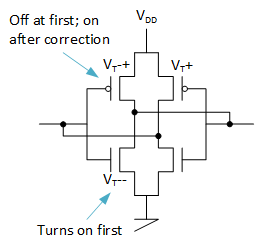
Each SRAM cell has a cross-coupled inverter pair. In theory, those inverters are matched, but, in fact, the thresholds have slightly different values. The two PMOS transistors have slightly different threshold voltages; that’s what determines how the thing will power up. The transistor with the smaller threshold will turn on first, tipping the latch in its direction. Take all of the cells and all of the pairs of transistors, each of which has a different threshold difference, and that’s how you get a unique signature for a specific chip.
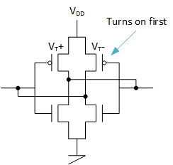
The farther those two PMOS thresholds are apart, the more stable this is going to be. On the other hand, if the two thresholds are really close in value, then you may get more power-up randomness. (In theory, if the thresholds agree exactly, then the outcome would be purely random – although I’m sure there’s a quantum explanation that would dispute that, or, at the very least, suggest that, “Hey, everything’s random anyway, so why are you whining?”)
But here’s the problem: let’s say you have a specific pair with a nice, wide gap between the two PMOS thresholds, and so it’s good and stable. Thanks to NBTI, over time, the smaller threshold of the two will get larger, closing the gap and increasing the read-out noise. At some point, the noise will exceed the capacity for error correction, and you’ll be in trouble. No one wants that.
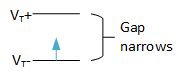
The fact that the transistor with the smaller threshold turns on first is key here: it will be the “on” transistor, while the one with the larger threshold will be off. Because it’s off, its threshold will not be affected. Only the low-threshold PMOS will be affected, raising its threshold and narrowing the threshold gap.
The Solution
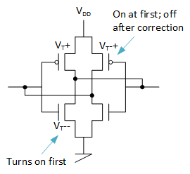
And therein lies the solution that Intrinsic ID says they have implemented. After reading the signature? They write to the memory with the opposite of the enrolled state. How do they know the opposite? Because they read the original enrolled state. But how can you count on that if it’s degrading?
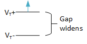
And that’s the magic: it’s not degrading. By writing the opposite states into every bit, now the transistor with the larger threshold, which didn’t turn on in the enrolled state, will be on. It will be experiencing NBTI over time. In this case, that’s a good thing: now you’re widening, not narrowing, the threshold gap, making noise less likely. In fact, by doing this, the devices literally become more stable over time.
Yes, the low-threshold PMOS will briefly be on after power-up, and its threshold can move a tad bit during that time. But, for the overwhelming bulk of time, the other PMOS will be on, so, even if the low-threshold PMOS tries to narrow the gap briefly at power-up, the other PMOS, due to being on longer, will outrun the low-threshold one, with the net gap widening over time.
What About NMOS?
All of this has assumed that the PMOS transistors control the start-up state. But then I started to wonder: what if one NMOS transistor has a lower threshold than either of the PMOS transistors? Now it will turn on first, regardless of the PMOS thresholds. I worked through that scenario, and I came up with the following. Note that I checked in with Intrinsic ID to see if this passed muster with them, and they thought it sounded reasonable, but that, from their experience, the PMOS does tend to be the controlling factor. But… if not… then:
- Let’s say that the controlling NMOS transistor is on the opposite inverter from the low-threshold PMOS. That would mean that both that NMOS and the low-threshold PMOS would be on in the enrolled state. When corrected, both that NMOS and PMOS would be off; the high-threshold PMOS would be on, and its threshold would rise over time, widening the PMOS-PMOS gap but changing nothing, since start-up is controlled by the NMOS-PMOS gap. (Here I use VT— to indicate the lowest low-threshold transistor, with VT-+ being the low-threshold transistor that’s not quite as low as the one with the VT–.)
- What about the other way around, where both the low-threshold NMOS and the low-threshold PMOS are on the same inverter, but the NMOS threshold is lower than the PMOS? Now the NMOS will still dominate the start-up state, and the low-threshold PMOS will be off in the enrolled state. When corrected, the low-threshold PMOS would be on, raising its threshold. In our original scenario, that was a bad thing, since it narrows the PMOS-PMOS gap. But, in this case, it’s not the PMOS-PMOS gap that’s controlling things: it’s the NMOS-PMOS gap. Because the PMOS threshold is rising (narrowing the PMOS-PMOS gap – but who cares?), the NMOS-PMOS gap is widening, again lowering startup noise.
- Now let’s say that the low-threshold NMOS and low-threshold PMOS have thresholds that are close enough that sometimes the NMOS wins and sometimes the PMOS wins. If they’re on opposite inverters, then they will “agree” on the startup state regardless of which one “wins” and there will be no noise. If they’re on the same inverter, then there will be noise – but it will be error-correctable if this is a rare scenario. If it’s error-correctable, then there will be a decided enrolled state that goes one way or the other. If the loaded correction (OK, “corrected” is being used two ways here – as error correction or as the state loaded to correct for NBTI; if I don’t use “error-corrected,” then we’re talking the latter) favors the low-threshold PMOS being on, then the noise will be reduced over time. If it favors the other one, then the low PMOS threshold will remain unchanged, which means the noise will remain but will not degrade. So if the noise was error-correctable to start with, it should remain so.
The bottom line is that none of these scenarios results in the noise getting worse. The noise either improves or remains constant.
So, yes, by this analysis, SRAM-based PUFs can suffer from long-term degradation. But, as Intrinsic ID tells it, that degradation can be more than accommodated: like any good aikido move, the damaging move is turned against the attacker, neutralizing the attack.
More info:


What do you think of this approach to thwarting PUF degradation?