


Ah, Ethernet… our good, reliable, trusty friend from way back. So trusty, in fact, that our cars may soon be running a version of Ethernet for all of the electrification stuff. Leveraging something tried and true should certainly go without a hitch, right?
Well, certainly as compared to coming up with something entirely new, perhaps. But what’s this Ethernet going to do in our cars?
Well, for one, it will help with the infotainment stuff. Lots of data coming in through a wireless portal, to be beamed back to screens stared at raptly by restless children in an attempt to quell the hail of spitballs that otherwise might provide the divertimento during a long road trip. Important stuff, no doubt, but not mission-critical. After all, you didn’t see the Walton kids getting all butt-hurt when they couldn’t watch the depression-era version of Spongebob, so life is possible without a screen.
But then there’s the other part: beaming time-sensitive control messages around between the various functional parts of the car. Yeah, the Waltons survived just fine without those messages too, but this isn’t simply an ADD issue: it’s how cars are evolving. This isn’t your ancestors’ Buick. So, if that’s the case, that messaging has got to be right. Messages need to get to the intended target in time to be useful. “Turn left, we’re veering off a cliff to the right!!!” doesn’t help if it arrives at the steering assembly right about the time when the hood latch is greeting the rocks below.
And that gets to an issue with legacy Ethernet, love it though we do: it’s a “best-effort” kind of system. It can’t guarantee that your message will arrive when you need it to. Amazon Prime does you no good here, sorry.
So… how do we send messages with deadlines on a network that doesn’t know deadlines from deadheads? This has been an ongoing effort, creating what’s referred to as a time-sensitive network, or TSN. Not sure if this is a good name, since what you really have is a hybrid network with some time-sensitive messages (“Turn left!!!”) and with time-insensitive messages (“This is gonna be the BEST DAY EVER!”*).
So how do you blend those together? The approach taken is to reserve certain time slots for messages that absolutely, positively have to get there on time. Identification of those messages is by priority. So, during that time slot, messages of that priority will be sent. After the slot, other messages are sent according to their various priorities.
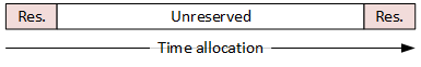
But the thing is, after those other messages start, then another time slot will approach. What if you start sending a low-priority packet in the unreserved time right before the designated slot, and it’s too long to finish sending by the time the priority slot arrives? It would be as if you reserved a time at the grocery-store checkout stand so that you could get in and get out quickly – except that the guy before you, who didn’t start during your time, ended up having 35 coupons, each of which needed to be verified and signed, and your time came and went with you standing there looking silly and knowing you’re going to be late back to work.
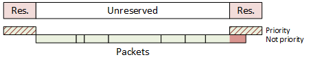
In order to avoid that, a guardband was added ahead of the reserved slot in order to block out some time where no new low-priority packet could be started. So you have a reserved slot, then open season for anything, then a time that might go empty, and then the next reserved slot.
![]()
If that guardband is long enough, you can pretty much guarantee that no packet that starts before the guardband will end after the guardband. That’s great – except for one thing: it’s a waste of bandwidth.
Now, for systems using a store-and-forward approach, where an entire message is received and stored before being sent on to the next destination, you can measure the length of the message to decide whether or not there’s time to send it before the critical time slot arrives. Got time to send 500 bits before the reserved slot? Then, if the stored message has less than 500 bits, go ahead and send it. If not, then wait. (Or find another message that does, but don’t take too long looking…) In this case, you no longer need the guardband, since you’re being deterministic about which packets will and won’t depart prior to the time slot.
But if your system is cut-through – that is to say, you receive a few bytes of a message and immediately start forwarding them on before you see the end of the packet – then you don’t know how long that packet is going to be. So you can’t tell whether or not to start sending it, and you no longer know whether or not it will encroach on the reserved slot. So you’ve still got a problem that might require a bandwidth-wasting guardband.
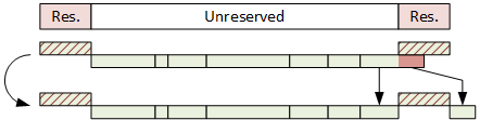
In order to address this, one final new critical feature has been added: the ability to interrupt a packet that’s in the middle of being sent in order to send some higher-priority packet at its duly appointed hour. The pre-empted packet continues being sent when the urgent stuff is complete. So now you can use the entire available bandwidth without having to throw some away “just in case.”
But some software has to perform this operation. It’s a matter of “shaping” the traffic as it’s being sent. Which is a product that Excelfore recently announced. It will be needed by sources of traffic as well as routers and switches to ensure that packets don’t bunch up at some bottleneck in the network.
Now… just because some company happens to be the first to send a press release about some new product doesn’t mean that they were the first to offer the product. So I asked Excelfore whether their traffic time-aware shaper (TAS) was new not only to them, but also to the industry.
According to Mark Singer, Director of Marketing at Excelfore, “Excelfore is aware that some TAS experiments have been shown, however we believe ours is the first commercially available.” So there you have it.
*For those of you without kids in a certain era, this is a Spongebob thing.
More info:


What do you think of Excelfore’s time-aware Ethernet traffic shaper?
In an automotive land where real-time events are tens of milliseconds, and $2 ethernet interfaces are 1 gigabit per second (possibly 10gbps) , it really seems somebody here is trying to sell a long unpopular bridge to nowhere.
And I’m really including that state of the art vision system (several channels of stereo vision, plus LIDAR and RADAR) back to the AI front end. When interfaces are dead cheap, you DO NOT design bandwidth critical, congestion managed links into the system. Both copper and fiber ethernet links are point-to-point, and congestion free by design. Don’t get stupid and design congestion points into an already clean design.
A big part of what fueled my first response was WTF, why are people thinking about designing unnecessary complexity into a mission critical high reliability application? IF these folks are thinking about replacing CAN Bus with Ethernet and using it as a primary navigation sensor bus, these folks are making a huge critical mistake. Ethernet switches, routers, bandwidth managers just become single points of failure that will take out the entire system, along with critical single point of failure cables, connectors, and the like for this botched system design.
Using a star design, with dedicated cables and ports for each sensor, gets rid of single points of failure critical to mission success. You can easily add interface redundancy at the system controller connectors, if you are building a redundant 3 way system controller, … or not, if that’s not important to the designer.
Given lives are at stake here, I’m not sure why anybody would purposefully design a system with single points of failure, or without a fair degree of redundancy.
How can we say that “Ethernet switches, routers … just become single points of failure”, and then follow immediately with “Using a star design, with dedicated cables and ports for each sensor, gets rid of single points of failure”? The center of any star design IS a single point of failure. This is why redundancy needs to be designed-in, with routing, as well as clock and message de-duplication at each network node. All of this is within the domain of the Ethernet TSN specs.
@Singer — you make some assumptions with “The center of any star design IS a single point of failure.” that are FALSE. It’s quite practical to make the center of the “star” physical interconnect topology be a fully redundant controller sharing interconnects, rather than some lame non-redundant controller that would as you assume be a single point of failure.
The statement “When interfaces are dead cheap, you DO NOT design bandwidth critical, congestion managed links into the system. Both copper and fiber ethernet links are point-to-point, and congestion free by design” is correct and appropriate for one point-to-point link. But it fails to provide a scalable approach to a network of many dozens of links. The amount of cabling will increase as a product of X times Y, with X (number of producers) and Y (number of consumers), and then we must add the physical lengths of the cables and the complexity of life-cycle management of long cables in a consumer product like the car.
Suggesting that each sensor adds it’s own cable running the full length from source to destination pushes an enormous burden onto the repair / replace infrastructure. This, without mention of what happens with sensors (producers) that have more than one destination (consumers) of their output. How does point-to-point work when the back-up camera in the rear bumper feeds both the ADAS computer under the hood and the head unit display in the dashboard? And when that back-up camera has problems do we really save complexity when we need to examine cable running through the trunk, down the whole length of the car and into the engine compartment to reach the ADAS unit, and then through the firewall to the dash/interior to reach the head unit display.
Perhaps we can belittle the impact of one back-up camera, but new cars are designed now with 10 or 12 cameras, with Lidar and Radar, not to mention the whole array of gyro tilt and accelerometers, temperature, moisture, weight and pressure sensors, and a host of other automotive sensors for internal combustion and electrical power management. All of these, placed throughout the vehicle — is it really efficient to have every one of them running cables all the way to each of their destinations, and then for the sake of redundancy doubling that number of cables?
Now add to that the question of time accuracy … in a car (or any other system platform) with 50 or more diverse sensors distributed around a perimeter of several meters. Suggesting that critical decision making being performed in multiple computing platforms using the inputs of some subset of these sensors somehow does not require synchronization to a common clock seems to ignore decades of best-practice in distributed design. How should we synchronize an ADAS computer with an anti-lock braking controller, an airbag controller and a seat-belt tensioning controller if sensors have only point-to-point connections and there is no general master clock ?
Far more rational than so many dozens of 10 meter cables, is one ring of high-bandwidth Ethernet TSN, providing a redundant master clock to any device that needs synchronization. Then each device can run a point-to-point cable only to the nearest network switch (or to the nearest two, for redundancy in links), and any device has but one or two cables that run a meter or less.
@Singer – you make some assumptions, as above, with “The amount of cabling will increase as a product of X times Y, with X (number of producers) and Y (number of consumers), and then we must add the physical lengths of the cables and the complexity of life-cycle management of long cables in a consumer product like the car.” That are FALSE.
Once again, interfaces, cables, and devices can quite easily be shared at the star interface for a fully redundant controller.
I believe the rest of your rant goes away with this clearification, as I certainly do not assert that an N-WAY mesh topology is a rational KISS solution with exponentially driving costs and complexitiy as you assert.
@Singer — You state “Suggesting that each sensor adds it’s own cable running the full length from source to destination pushes an enormous burden onto the repair / replace infrastructure. This, without mention of what happens with sensors (producers) that have more than one destination (consumers) of their output. How does point-to-point work when the back-up camera in the rear bumper feeds both the ADAS computer under the hood and the head unit display in the dashboard? And when that back-up camera has problems do we really save complexity when we need to examine cable running through the trunk, down the whole length of the car and into the engine compartment to reach the ADAS unit, and then through the firewall to the dash/interior to reach the head unit display. ”
Actually cables are far cheaper, easier to debug, and significantly more reliable than active electronics solutions (switches, routers, flowlimiters, etc) that along with the increased cable connections also add a significant number of new component connections on the various PCB’s that are ALL subject to lifetime failure rate probabilities that WILL IMPACT MTBF. Especially thermal cycling and vibration of SMT parts.
It doesn’t take much to design self diagnosis into point to point cables. Length of cables doesn’t significantly affect MTBF … however increasing the number of cable connections does, and that is what you are proposing by increasing the number of active devices in the system.
As for your backup camera argument … if the camera is shared, there will already be those additional data connections. I would suggest terminating the camera at the redundant controller (ADAS computer), and have it forward video streams to the in dash entertainment controller for display, rather than adding a new cable and active electronics to that data path. Significantly lower MTBF and cost.
Again, we can easily argue that reduced connections, reduced electronics will improve reliability, MTBF, and MTTR.
oh … and your “ring” is a single point of failure that takes out every system and sensor.
STAR with redundant electrical interfaces sharing physical connectors, reduces failure points, and has NO single point of failure that takes out all the sensors … no shared cables for sensors, no shared electronics for sensors. Multiple sensors can fail. Multiple connections can fail. But none are conditional on a functional “ring” physical topology that if compromised, will take out the entire system.
@Signer — you state “Far more rational than so many dozens of 10 meter cables, is one ring of high-bandwidth Ethernet TSN, providing a redundant master clock to any device that needs synchronization. Then each device can run a point-to-point cable only to the nearest network switch (or to the nearest two, for redundancy in links), and any device has but one or two cables that run a meter or less.”
I strongly differ … as you are obviously defending a significantly more complex design, that is both more expensive, and has significantly higher complexity with reduced MTBF in comparison with a KISS STAR physical topology.
@ Singer — what I stated, and you missed was “you can easily add interface redundancy at the system controller connectors, if you are building a redundant 3 way system controller, … or not, if that’s not important to the designer.”
It’s relatively easy to introduce a safe voting controlled switch between the ethernet port, and each redundant controller that needs access to the resource. This can easily include a broadcast design, where every redundant controller can receive packets from the sensor for redundant parallel processing of the data stream, but only one elected master has transmission rights to control the sensor.
There are other options, none of which require the complexity of a complex multiple ethernet networks with switches, routers, and flow limiters.
You seem to be defending an existing high complexity design … good luck with that.
At the end of the day, it comes down to how many concurrent failures are required to take the system off line.
A good system design will be exceptionally robust, remaining functional and safe with multiple failures.
Probably as few as two failed connections in @Singer’s ring design, are all that is needed to take the system off line.
Most Ring typologies claim to be able to be self healing in the face of a single failure. The real question is what is the minimum number of failures in the ring, before the application fails? Depending on the connectors used to implement the ring, that could be as few as one compromised connector with water in it, that takes out ALL connections at that device … which could be pretty fatal if it’s the ADAS connection.
This pretty much means that in a STAR design, each sensor terminates at the ADAS with a separate connector, so that a single wet connector doesn’t take the system down.
KISS also requires that you THINK. That you have a clear design process and reliability requirements. That you have a clear system failure analysis process to protect critical operations in the face of multiple failures.
Fun, high tech, things like rings may look good on paper, and even support presenting those papers at conferences. They are certainly new, fun, research projects that appear to extend the state of the art. And everybody might even sign on for the fun, and believe that it’s the best choice for the product.
But at the end of the day, does KISS promote a “better design” that is more robust in the face of multiple failures, with significantly lower MTBF and MTTR.