

Time seems to be passing extremely fast these days. Every time I blink, another week passes by; every time I sneeze, I lose another month; and every time I… but we digress. Just a few weeks ago (or possibly several months ago the way things are going), someone posted a comment to one of my columns saying they were surprised they hadn’t seen an update regarding the status of my HRRG Computer project here on EE Journal.
If you were to ask me, I’d probably say that I spend a lot of time working on my hobby projects. However, I fear the truth of the matter is that I spend more time dilly-dallying, wiffle-waffling, and generally procrastinating than actually doing the work. As a result, some of my projects have stretched out for years, while others have dragged on for decades.
One such scheme is my Heath Robinson Rube Goldberg (HRRG) computer, which is named in honor of the English cartoonist, illustrator, and artist William Heath Robinson (1872-1944) and his American counterpart Reuben Lucius Goldberg (1883-1970). These gentlemen were famed for creating illustrations of cunning contraptions whose goals were to perform seemingly simple tasks, but whose realizations performed said tasks in exceedingly convoluted ways.
As the Wikipedia tells us: “A Rube Goldberg machine, named after American cartoonist Rube Goldberg, is a chain reaction-type machine or contraption intentionally designed to perform a simple task in an indirect and overly complicated way.” You can find all sorts of Rube Goldberg machines on YouTube. One I keep on returning to when I feel like taking a little breather is the This Too Shall Pass video by OK Go.
Almost since I graduated university and started my first job as a member of a team designing central processing units (CPUs) for mainframe computers, I toyed with the idea of constructing a relay-based machine of my own devising. This project hovered around at the back of (what I laughingly call) my mind until the early 2000s when I ran across a mega-cool relay-based computer created by Professor Harry Porter III.
On the one hand, this stimulated me into action. On the other hand, it gave me pause for thought because I didn’t want to do something that someone else had already done, if you see what I mean. One thing I really liked about Harry’s machine was the way he presented it as a collection of wall-mounted, glass-fronted wooden cabinets (I wasn’t so keen regarding the bundles of wires linking these cabinets together).
All of this spawned my idea to create the HRRG as a mixed-technology computer. The HRRG is also intended to be presented as a collection of wall-mounted, glass-fronted wooden cabinets. In this case, however, each cabinet would feature a different implementation technology, including relays, vacuum tubes, discrete transistors, and “jellybean” (SN7400-series) ICs, along with magnetic logic, pneumatic logic, and hydraulic logic, to name but a few of the contenders.
I’d originally conceived the HRRG being an 8-bit machine (some of my early thoughts are documented on the DIY Calculator website). Along the way, however, I was joined in this project by my chum Joe Farr, who hangs his hat in the UK. At some stage, we decided that a 4-bit machine would increase the fun and frivolity, while also making the HRRG more interesting as an educational tool (in addition to its 4-bit data bus, the HRRG sports a 12-bit address bus, thereby allowing it to address 2^12 = 4,096 of our 4-bit words). More recently, Joe and I have been joined on our quest by Nils van den Heuvel, who hails from the Netherlands. Having run across some of my earlier HRRG Computer cogitations and ruminations, Nils set out to create a gate-and-register-level implementation of the HRRG in an FPGA. The things he discovered along the way caused the three of us to rethink and refine a lot of nitty-gritty details.
The current state of play is as follows. The CPUs in the first 8-bit microprocessors had a single register called an accumulator (ACC) in which they stored (“accumulated”) the results from their computations. For example, a program might load a number from memory into the ACC, add a second number from memory to the value currently in the ACC, and then do something like storing the result back into the memory, or perhaps make a decision based on the size of the result.
The next generation of 8-bit microprocessors went in all sorts of directions, architecturally speaking. Some designers opted for dual accumulators while others decided to use a bunch of general-purpose registers. One of the things that made these designers’ lives easier is that their 8-bit words supported 2^8 = 256 different instructions. This allowed them to use different instructions to implement different addressing modes. For example, “LDA $35” would use the immediate addressing mode to load the hexadecimal value $35 into the accumulator. By comparison, assuming a 16-bit address space, “LDA [$0035]” would use the absolute addressing mode to load the accumulator with whatever 8-bit value was to be found in the memory at hexadecimal address $0035. Each of these instructions would have its own 8-bit “opcode” (short for “operation code”), which is the portion of the instruction that specifies the operation to be performed.
Since we’ve made the decision to use 4-bit words, this limits us to supporting only 2^4 = 16 instructions. Similarly, due to the way we’ve decided to implement things, it limits us to supporting only 16 different registers in the CPU.
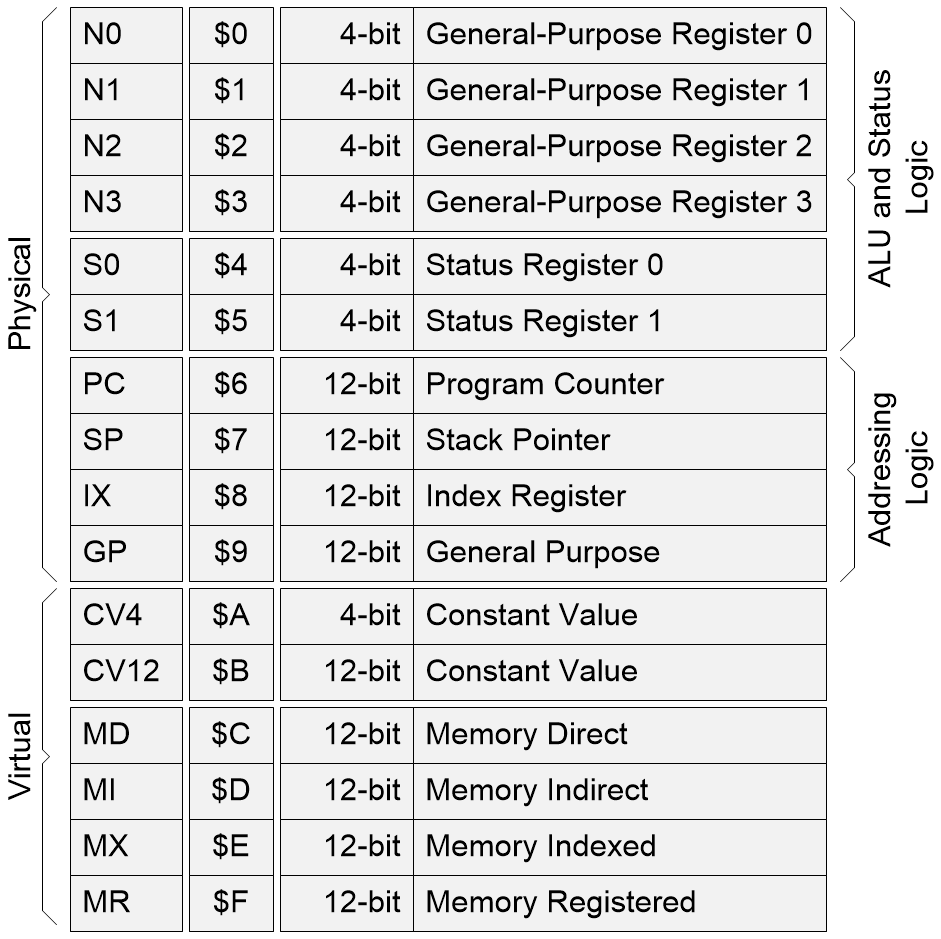
The 4-bit HRRG Computer’s 16 registers (Image source: Max, Joe, and Nils)
One of the things I think is quite clever—and something I’ve never seen before (or, at least, I’ve never seen it presented in quite this way before)—is the use of what we’ve called “virtual registers” to implement our versions of the addressing modes. For example, our “constant” modes are equivalent to traditional “immediate” addressing, while our “direct” mode is equivalent to traditional “absolute” addressing.
You may have observed that we have two status registers called S0 and S1. We had to do this because we have more than four status bits. One of the interesting aspects of this is that we can treat these two 4-bit registers as a single 8-bit register when it comes to implementing our various jump instructions.
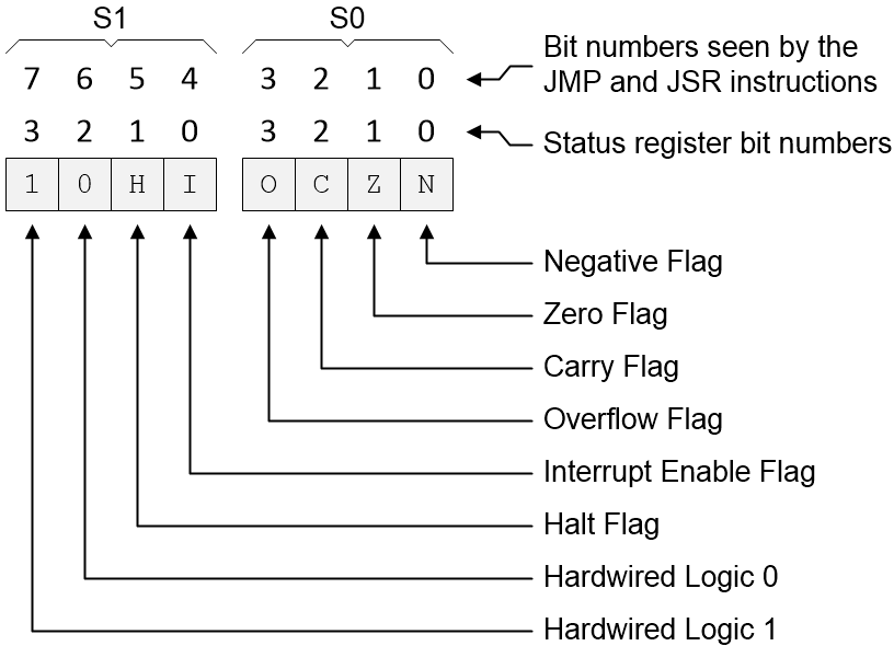
The 4-bit HRRG Computer’s status registers (Image source: Max, Joe, and Nils)
Things really start to get exciting when we come to the instruction set. Remember that our 4-bit word supports only 2^4 = 16 instructions. If you were doing this, which instructions would you choose? In our case, we opted for the ones shown below.
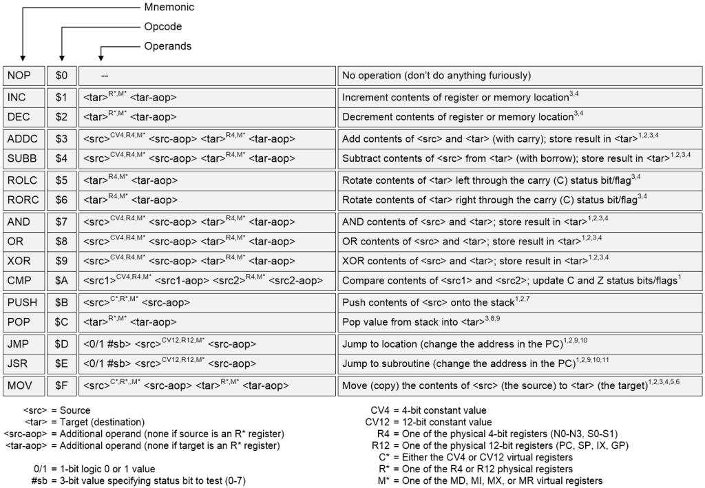
The 4-bit HRRG Computer’s instruction set (Image source: Max, Joe, and Nils)
It has to be acknowledged that this does take some time to wrap one’s brain around, but it soon starts to make sense when you get into the swing of things. Let’s take the INC instruction (hexadecimal $1), for example. If we combine this with one of the physical registers, like the 4-bit general-purpose register N3, then our machine code would be “$1 $3,” which tells the HRRG to “Increment the contents of register N3.” By comparison, if we wanted to increment the contents of memory location $003, we would use the virtual Memory Direct ($C) accompanied by the target address, so our machine code would now be “$1 $C $003.”
Apart from anything else, this illustrates the fact that most of the HRRG’s instructions can operate on both registers and memory, which is really quite powerful. Using the machine code “$3 $A $3 $C $003,” for example, we could ADDC ($3) the 4-bit constant ($A) value ($3) to the contents of the memory ($C) at address $003, which is also the address where the result will be stored.
In the case of addition, we could have decided to support both ADD (“add without carry”) and ADDC (“add with carry”). Since we are instruction limited, however, we opted for ADDC because it’s a lot easier to finagle an ADD from an ADDC than the other way round. Similarly for SUB (“subtract without borrow”) and SUBB (“subtract with borrow”).
To be honest, I could waffle on about this for hours, which goes some way to explain why the instruction set illustration references so many notes that explain things in excruciating detail. For the purposes of this column, however, I will spare you the nitty gritty details.
One thing I would like to do is give a shout out to Nils. Prior to his joining us, Joe and I had bent over backwards using words to try to describe the way in which 4-bit and 12-bit sources interacted with 4-bit and 12-bit targets. Nils quickly came up with the following diagram, which makes everything clear.
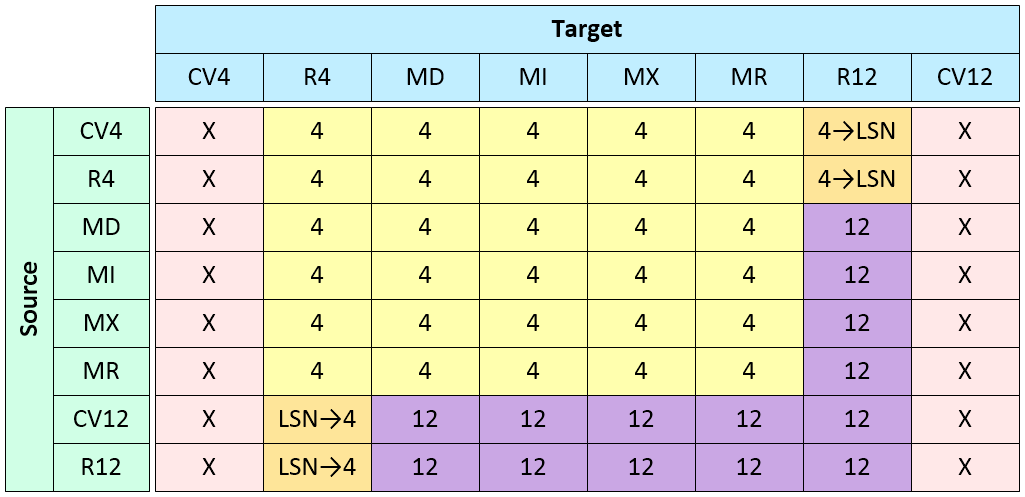
Graphical depiction of the interactions between 4-bit/12-bit sources and targets (Image source: Max, Joe, and Nils)
What this tells us at a glance is that if a 12-bit register (R12) is copied to a 4-bit target (R4) for example, then only the least-significant nibble (LSN) will be copied. Brilliant!
Meanwhile, Joe has done a lot of work with respect to an assembler, which he implemented in such a way as to make it look like a virtual Sperry Univac Uniscope 200 computer terminal (Joe chose this little beauty because he happens to have a real one in his workshop).
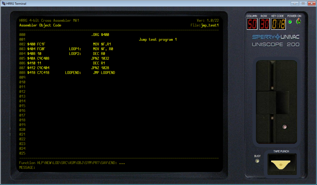
The 4-bit HRRG Computer’s assembler (Image source: Joe Farr)
Observe the yellow triangle protruding out of the bottom right-hand corner of the virtual Uniscope 200. This is the end of a piece of virtual paper tape. Once you’ve assembled a program to your satisfaction, you can save it out as a virtual paper tape with sound effects and everything. Furthermore, Joe has created an extremely cool emulator as illustrated below.
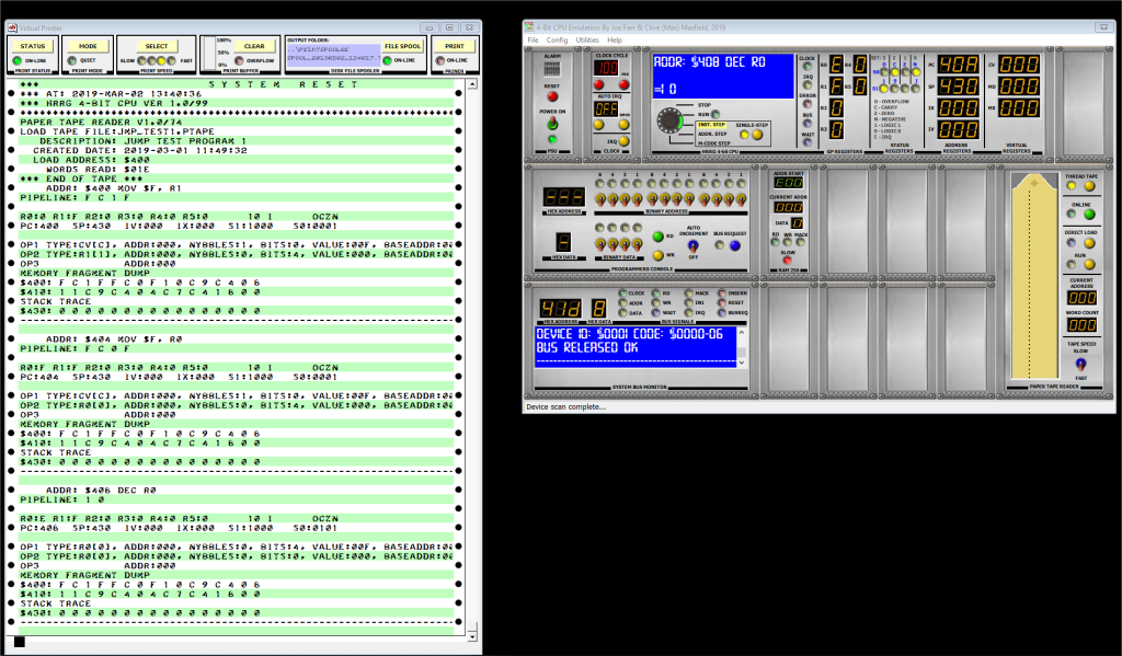
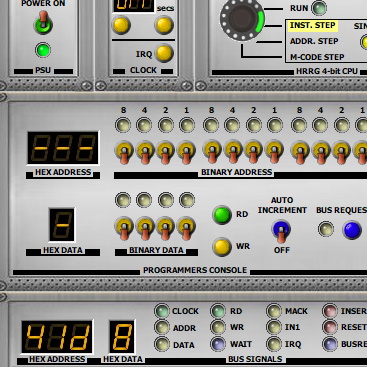
The 4-bit HRRG Computer Emulator (Image source: Joe Farr)
In this case, you can program the virtual HRRG using the switches on its front panel. Alternatively, you can load a machine code program from a virtual paper tape that you previously created using the aforementioned assembler. You can also keep a record of everything going on by activating the virtual printer with its green-and-white striped fanfold paper as shown to the left of the illustration above.
Do you recall my mentioning that we are hoping the 4-bit HRRG Computer will find an educational role? Well, even in my most excitable moments, I’m aware that it’s unlikely that a high-school computer class would have the time and energy (and money) to build a full-up HRRG. However, they could certainly create something like a single 4-bit word of memory using the technology of their choice. Our idea is that they could then connect their physical “cabinet” to our emulator to see their creation working in the context of the rest of the system.
Once again, I could waffle on about this for hours (and I’m sure I will at some stage in the future). For the moment, however, you may consider yourself as having been brought up to date as to the latest state of play regarding the 4-bit HRRG Computer. As always, I welcome your comments, questions, and suggestions.


Someone just emailed me to share an awesome YouTube video that talks about a wide variety of relay computers: https://youtu.be/_j544ELauus
Max,
I suspect you may have played a part in the design and creation of the USN MK 112 Torpedo Fire Control Computer I had the unfortunate task I keeping running on each patrol.
The D*&N thing was definitely a Rube Goldberg quality contraption. A hybrid Analog/Digital device of most unreliable caliber. Its construction was a perplexing mixture of analog synchro servos and an unwholly number of big clunky relays. (Each about the size of a 4 oz tomato paste can.) Every time the monster went down and required contact with the manufacture, the standard answer was, “Sorry that engineer no longer works for us.”
It was a factor in my decision to cut my Naval career short, even though I loved the rest of the submarine service.
That USN MK 112 sounds awesome in a “I’m glad I don’t have to use it myself” sort of way — I wish I could see one in the flesh. Thanks for sharing — Max