

As I mentioned a couple of weeks ago in my Why, Hello FPGA and AI — How Nice to See You Together! column, on May 20th I gave my What the FAQ is an FPGA? presentation at the Embedded Online Conference. I’m sure it goes without saying (but I’ll say it anyway) that this was an awesomely awesome presentation that will doubtless be talked about for generations to come, and I say that as someone who is not biased in any way, so it must be true.
Just for giggles and grins, following the main part of the presentation, we bounced around introducing and considering various topics in the context of FPGAs, like radiation, metastability, switch bounce, and artificial intelligence (AI)/machine learning (ML).
It was while I was talking about metastability that my mind began to wander, as is its wont, and I started thinking about “this and that.” One of my meandering musings involved metastability. “Suppose someone asked us to design a safety-critical and mission-critical FPGA-based system to monitor the state of an asynchronous “big red button” and to perform some action when that button was pressed. The main thing is that something (“End of the world as we know it!”) horrible will happen if we instigate the action before the button is pressed or if we fail to trigger the action within say 50 milliseconds (ms) after the button has been pressed.
Metastability can occur when an asynchronous signal — like our switch being pressed — is accessed by a synchronous system like a microcontroller (MCU) or FPGA. One of the funny things about metastability is how few embedded designers whose systems are MCU-based are even aware it exists (we’ll discuss why this is the case later in this column).
This can be a tricky topic to wrap one’s brain around, so please forgive me for my step-by-step approach. Let’s start by considering the case where our asynchronous signal is being loaded into a D-type flip-flop inside the FPGA as illustrated below:
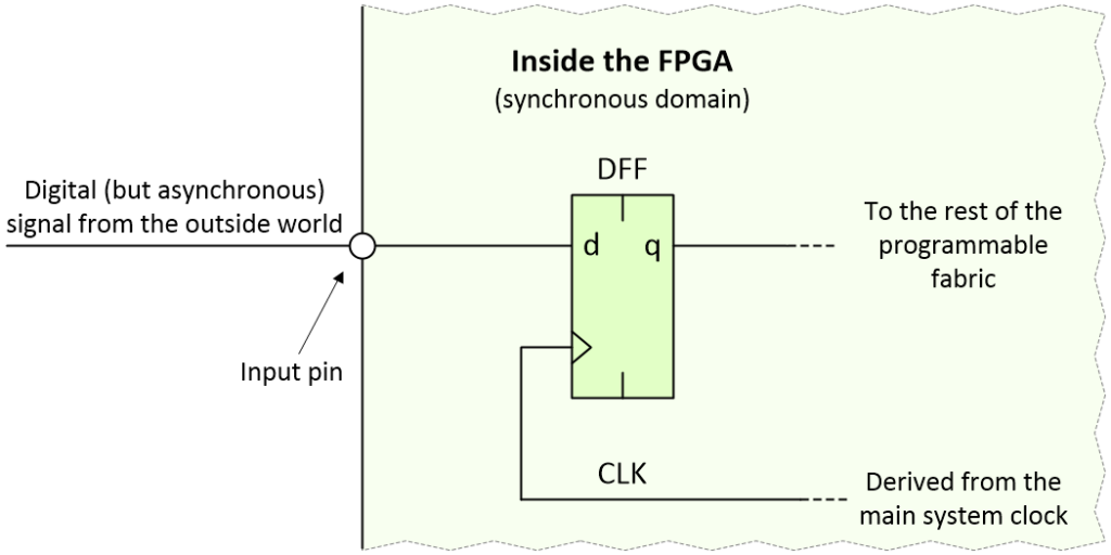
Loading an asynchronous signal into an FPGA (Image source: Max Maxfield)
The thing about pushbutton switches in general, and our pushbutton switch in particular, is that any changes on their outputs are relatively infrequent in the scheme of things, especially when compared to an FPGA clock running at, say, 100 MHz. The fastest we might reasonably expect a regular pushbutton switch to be pressed could be a couple of times a second. In the case of our safety-critical and mission-critical system, the pushbutton switch may be pressed only once in the operator’s lifetime, in which case it behooves us to get things right.
Let’s assume that the clock signal loading the D-type flip-flop is free-running. If the asynchronous transition occurs before an active clock edge, the new value will be loaded into the flip-flop. If the transition occurs after an active clock edge, then it will be loaded into the flip-flip on the next clock edge, which will occur 10 nanoseconds (ns) after the previous edge in the case of our 100 MHz clock.
The problem occurs if the asynchronous signal transitions too close to an active clock edge. In this case, it may violate the flip-flop’s setup or hold violation times and cause the little scamp to enter a metastable condition. This usually involves the output of the flip-flip taking on an intermediate voltage level, but there’s also the possibility that it starts to oscillate.
If it does start to oscillate, then tiny variations in the gates forming the flip-flop will eventually cause it to settle into a good (albeit unknown) logic 0 or 1 state. In the case of the intermediate voltage, this is an example of unstable equilibrium, which will persist for some amount of time until some minute disturbance causes it to “collapse,” at which time the flip-flop will randomly end up in a good 0 or 1 state. How long this takes may vary from flop-to-flop and from violation-to-violation, but the data sheet will specify a “recovery time” after which the flip-flop “should” have settled into a good (if unknown) state (we’ll return to consider my use of the word “should” in a little while).
Remember that the output from our flip-flop may feed multiple other devices in the form of combinatorial logic and/or other register elements and/or memory cells. Our mission in life is to prevent any metastability from working its way into the rest of the system leaving a trail of confusion and disruption in its wake.
A very common approach is to use a two-stage synchronizer as illustrated below:
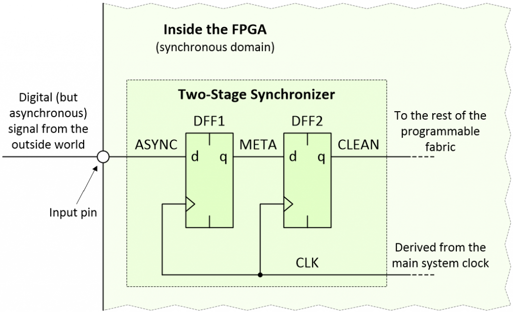
Using a two-stage synchronizer (Image source: Max Maxfield)
For the purposes of these discussions, I’ve named the three signals of interest ASYNC (this is our asynchronous signal), META (this signal may enter a metastable state), and CLEAN (this signal should be cleared of any metastability).
Now, let’s suppose that someone pushes our button outside of the first flip-flip’s timing violation window and that our ASYNC signal transitions from its original value (green) to its new value (blue) as illustrated below (where ts = setup time, th = hold time, and tp = register propagation delay):
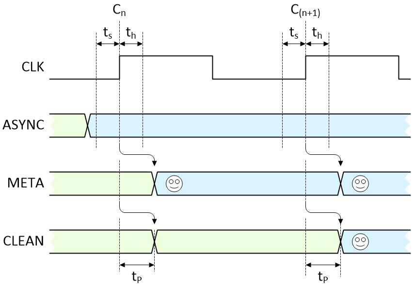
No violations. All is good with the world (Image source: Max Maxfield)
The first active clock edge (Cn) following the switch transition loads the new value we want (smiley face) into the first flip-flop, and it appears on the META signal after that flip-flop’s propagation delay. Similarly, the next active clock edge (C(n+1)) loads the value on META into the second flip-flop, and it subsequently appears on the CLEAN signal following that flip-flop’s propagation delay.
The end result is that the signal we wanted now takes two clocks to wend its way into the system and become available to us. Let’s now consider what happens if our asynchronous signal triggers a setup or hold violation. In fact, there are two possibilities; the first is illustrated below:
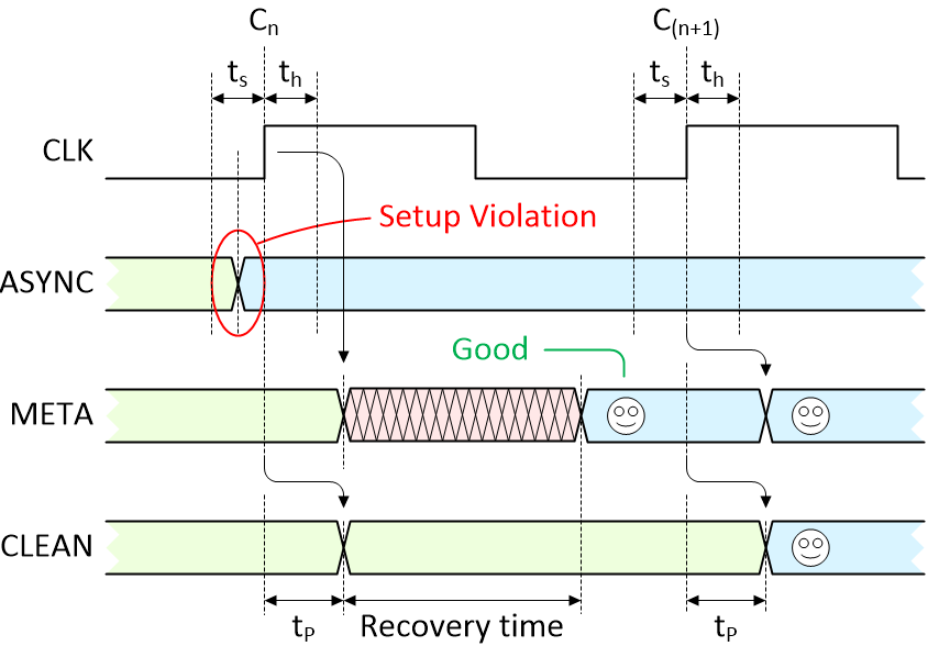
There is a violation, but the flip-flop settles into the desired state anyway (Image source: Max Maxfield)
As we see, the transition on the ASYNC signal causes the META output from the first flip-flop to enter a metastable state. At some time before the end of the recovery time, the metastable condition collapses and — by chance — the first flip-flop ends up containing the value we were hoping for (happy face). In this case, things are just the same as if there were no violation at all, and we see the signal we are looking for appear on the CLEAN signal after the second clock.
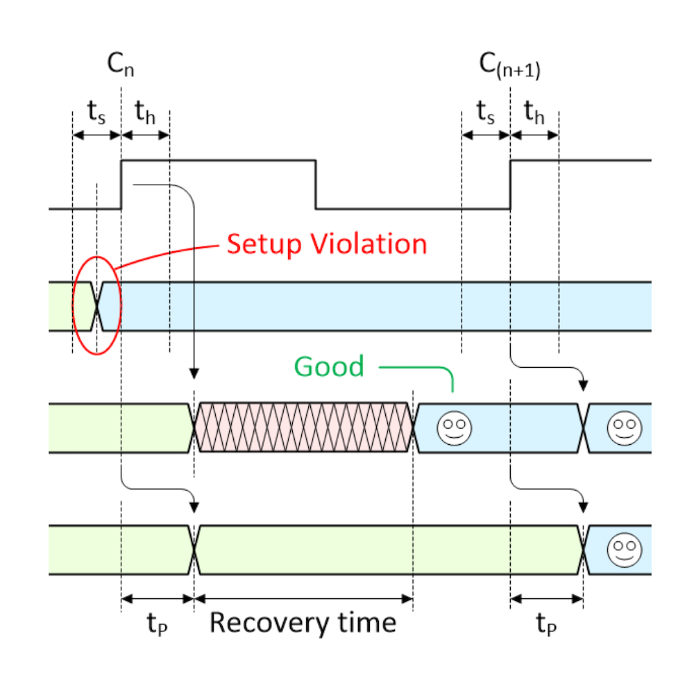
But now consider the “almost” worst-case scenario as illustrated below (once again, we’ll return to consider my use of the word “almost” in a little while):
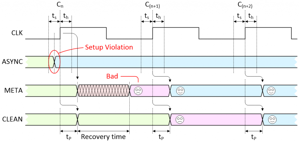
There is a violation and the flip-flop settles in the undesired state (Image source: Max Maxfield)
This is where things start to get interesting. As before, the transition on the ASYNC signal triggers a violation that causes the META signal to enter a metastable state. At some time before the end of the recovery time, the metastable condition collapses but — by chance — the first flip-flop ends up containing the old value that we no longer want to see (sad face).
On the next active clock edge (C(n+1)), the new (desired) value on ASYNC is finally loaded into the first flip-flop and appears on the META signal (happy face), but the old (undesired) value on META is loaded into the second flip-flop and appears on the CLEAN signal (sad face). It’s not until the next active clock edge (C(n+2)) that the new (desired) value from ASYNC finally works its way through to the CLEAN signal (happy face).
This is typically the point where some bright spark will ask, “But what happens if the violation occurs on the second or third clock edges?” No problemo. Remember that this is a free-running clock, so if the transition on the ASYNC signal doesn’t occur — and cause a violation — until the second or third clock edges in our diagram, then that clock essentially becomes our first clock and off we go again.
The bottom line is that this “almost” worst-case scenario requires three clocks before a transition on ASYNC works its way through to the CLEAN signal, ready to be used by the rest of the system.
So, why do I keep on saying things like “should” and “almost”? Well, the problem is that, unlike things such as maximum propagation delays, which tend to behave themselves, the recovery times for flip-flops are somewhat more statistical in nature. That is, there’s always a chance, albeit small, that the metastable condition will persist beyond the recovery time. There’s even a chance it will persist until the next active clock edge, in which case the metastability may propagate down the line and “infect” the second flip-flop.
One solution is to add another flip-flop to form a three-stage synchronizer. I’ve heard rumors that some designers add even more stages, but I’ve never met one, so I cannot attest to the veracity of this possibility.
How do we know how many stages to use? The math makes my head hurt, but you can find out more in this paper, which was written by my chum Adam Taylor, or in this paper, which was written by someone at Intel (Altera, as was).
In addition to being used to access asynchronous signals from improbably sized “big red switches,” synchronizers of this ilk are commonly used inside FPGAs and System-on-Chip (SoC) devices with regard to clock domain crossings (CDCs). This refers to the fact that large designs may involve multiple clock domains. If a data signal is traversing from one domain to another, it may appear asynchronous on the incoming clock boundary; hence the fact that a synchronizer may be employed.
As always, I now have all sorts of random thoughts bouncing around my poor old noggin; for example:
Random Thought #1: My chum, the aforementioned Adam Taylor, tells me that there’s more to all this than meets the eye (like placement of any synchronizers relative to the I/O pins), and that the folks at Xilinx provide a library of parameterized macros, some of which perform synchronizer functions (check out Adam’s MicroZed Chronicles column on this topic).
Random Thought #2: We just spent a lot of time considering a single transition on our big red switch, but — as we all know — switches bounce; bouncy, bouncy, bouncy; that’s what they do. So how will our two-stage synchronizer cope with noise spikes or a dirty bouncing signal? (See also Ultimate Guide to Switch Debounce.)
Random Thought #3: Why are so few embedded systems designers who devote themselves to creating MCU-based systems aware of the problems associated with metastability? I must admit that, until recently, whenever I’ve created a sketch (program) for use with one of my Arduino-based hobby projects, I’ve happily read values from the digital inputs without giving metastability a second thought. The answer is that the clever guys and gals who designed the MCU itself have already handled this for us.
Take the Arduino Uno, for example. This little scamp uses the ATmega328P MCU. If we look at the 294-page ATmega328P data sheet, what do we see on Page 63 regarding the digital input/output (I/O) pins? Why, “Good golly Miss Molly,” it’s a diagram of a single pin showing non-other than our trusty two-stage synchronizer being driven by a CLKI/O signal. Meanwhile, in the chart on Page 34, we see that CLKI/O is a free-running clock.
This means that when a digital I/O has been set up as an input, the CLKI/O signal is constantly reading the value on that pin and passing it through its two-stage synchronizer. In turn, this means that when I issue a digitalRead() command, I’m not actually accessing the value on the pin; instead, I’m reading whatever value is currently “ready and waiting” on the output from the two-stage synchronizer.
Random Thought #4: Some people might say that if you add enough stages to your synchronizer, then the chances of metastability working their way through to the synchronizer’s output are “statistically insignificant.” Well, that’s as may be, but suppose the purpose of our big red button were to save the planet from being demolished to make way for a hyperspace bypass? Just how “insignificant” would “statistically insignificant” be in this sort of situation (and don’t think of driving me to talk about infinite improbabilities)?
This led me to ponder what would happen if we were to essentially create a triple modular redundancy (TMR) implementation of the two-stage synchronizers — that is, take three two-stage synchronizers and wire them in parallel, but instead of having a voting circuit, use … well, something. The problem occurs to me that if we were to feed the outputs of all three synchronizers into an AND gate, for example, then if two of the inputs were 1 and the other was metastable, that metastability could propagate through the gate. But what about… No! Enough! My head hurts! What do you think?


Hi Max,
Your musings on a “big red button” immediately caused this Daffy gem to pop into my brain:
https://www.youtube.com/watch?v=MlrCMK14zHs
“Not the wed one! Don’t ever push the wed one!” has been part of my lexicon since my (misspent?) youth watching these cartoons.
I’ve said it before, and I’ll say it again, there are very few things that happen in life for which Bugs Bunny and friends don;t have something appropriate to say LOL
Max, I can identify with your comment “One of the funny things about metastability is how few embedded designers whose systems are MCU-based are even aware it exists.” I have been stunned many times by experienced design engineers who deny that metastability even exists. I would explain to them that when the “CLEAN” signal commands multiple state machine inputs to “Turn Left” but some inputs hear “Turn Right”, that a state of chaos or lock up may result. If the state machine is controlling a Tesla or a SpaceX Falcon, clearly the result might lead to disaster. The key to designing synchronizers to insure that the MTBF is greater than the lifespan of the device. Thank you, Max, for retelling the metastability story. We as must continue to tell this story over and over, passing it down to future generations.
Hi John — thanks so much for taking the time to post your comment. This is one of those areas where things can seem so simple (“Let’s read the state of this switch”), but then things like switch bounce and metastability rear their ugly heads. I would love to be omniscient and know the true story as to how the original system pioneers first discovered these problems and the various approaches they used to address them, but I fear the power of omniscience is possessed only by … my mother LOL
Hi Max, I also would be interested to know the true story as to how the original system pioneers first discovered metastability. I remember the Intel 8048 failures due to metastability with subsequent revision. Steve Golson sited synchronizer failures due to metastability with LINC, DEC PDP-11/45, DEC PDP-15, Space Shuttle PASS, AMD Am29000, AMD 9513, AMD 9519, Zilog Z-80 SIO, Intel 8048, Intel 8202, Intel 8085, Honeywell 516 / ARPANET IMP and Synopsys DW04_sync, in his paper: Synchronization and Metastability, trilobyte.com/pdf/golson_snug14.pdf . What is your mother’s experience with metastability?
Hi John, IBM announced System 360/Mod67 in August 1965, the 2846 2846 Channel Controller had a bad case of metastability in the request arbiter. It was found that if the arrival time of a request and the clock were within a narrow window that the latch would oscillate similar to cross coupled inverters, which was dubbed “unity gain state” that looked like a “rooster tail” on a scope.
A few years later in the NASA Control Center in Houston interrupt requests would occasionally get “lost” and it was deduced that it was the same situation. Adding hysteresis to the synchronizer feedback solved the problem. And the moon shot was a success.
When I worked as a computer designer for the now defunct Hughes Aircraft from 1970-1979, two stage synchronizers and Schmitt trigger + multiple flip-flop debouncers were the standard for all asynchronous and bouncing inputs to any digital system. So the problems were well known by then, at least in the “defense” industry.
When I taught digital design at UC Berkeley from 1980-1986, one of my standard lab assignments was to get a circuit into meta-stability, with another lab to observe switch bounce (using 74XX series chips and a 100 MHz analog scope). Lectures covered the setup-hold violations, and the physical switch bounce problems.
Getting visibility of these behaviours in an MCU circuit operating at GHz is probably not possible in a college lab, but there is no reason not to repeat these lab exercises with slower chips and modern scopes.
Hi Mike — I was just thinking that if any of us were to fall thru a time tunnel and find ourselves in the 1950s, the amount of information we have in our heads would make us look like heroes LOL