


I have seen the future of electronic design. It is both awesome and scary. I’m too young for all this excitement. I have much to impart. Before we proceed further, however, let’s first remind ourselves as to the way things were in ye olden days, by which—as terrifying as it seems—I mean prior to 2023.
When I was a young sprout deep in the mists of time that we used to call the early 1970s, I created all my designs using discrete components soldered onto Veroboard (a.k.a. stripboard). In the case of those rare hobby projects that came equipped with printed circuit boards (PCBs), these were typically single-sided—occasionally double-sided—with incredibly wide copper tracks as compared to today’s offerings.
I remember sketching homegrown schematics using pencil and paper, then painstakingly transferring these circuits to the stripboard, which invariably involved cutting lots of tracks. In my case, this also invariably involved adding jumpers to reconnect incorrectly cut tracks.
Later, in the early 1980s, the company I worked for invested in a PCB layout workstation. Although archaic by today’s standards, this was a beauty to behold back in the day. The workstation itself formed an integral part of a desk, upon which were mounted two honking big cathode ray tube (CRT) monitors. One of these monitors provided a glorious color display, while the other made its presence felt in inglorious black-and-white. We used the latter to input command-line instructions to do things like place a pad at a certain XY location, or to create a segment of a track on the current layer between a pair of XY locations. On hitting the <ENTER> key, that segment would be drawn on the color monitor.
That’s right—we literally created our PCB layouts one track segment at a time. The sad thing is that this was so much better than what had gone before. We scoffed at our elders who had been obliged to create their PCB layouts by sticking strips of tape onto mylar films.
I just remembered that this workstation came with myriad humongous manuals. In my mind’s eye, I can see a long shelf packed end-to-end with these hefty tomes. I’m contrasting this to today when you are lucky to be presented with a Post-it note sized “Quick Start” that instructs you to plug the device in and follow the on-screen instructions.
I also just remembered that one day the color monitor started flashing a message in super-large characters saying something like “ERROR 804.” When we eventually located the appropriate “Error Codes” manual and tracked down the 804 entry it read something like, “System overheating.” We certainly couldn’t fault the manual writer for lack of accuracy in this pithy entry because—by the time we returned our gaze to the workstation—the system was on fire.
I tell you; I could write a book about all the things I’ve seen. Speaking of which, I remember seeing the first PCB layout tools with push-and-shove routing circa the late 1990s and early 2000s. This allowed the operator to use the mouse cursor to drag vias and track segments, with all attached and surrounding elements, across multiple layers, re-working themselves on-the-fly. I thought this technology was incredibly clever. I fear that I failed to fully grasp the applicability of the longstanding American slang idiom, “You ain’t seen nothin’ yet!”
I was just about to say, “I’ve seen it all now,” but the day is yet young. The thing is that I was chatting with Matthias Wagner (Chief Skywalker) and Kerry Chayka (Blackbelt Hardware Engineer) at Flux.ai
You may recall my talking about GitHub Copilot in an earlier column: Using Generative AI for Refactoring and Debugging Code Cuts Debugging Time in Half! This little scamp is a cloud-based artificial intelligence (AI) tool developed by GitHub and OpenAI to assist users of Visual Studio Code. GitHub Copilot helps embedded software developers to capture their code. It observes any comments and code they enter and offers suggestions for what comes next.
Well, Flux Copilot does much the same thing for electronic design and PCB layout. The easiest way for me to convey a high-level view of what all of this is about is to show you a screenshot.
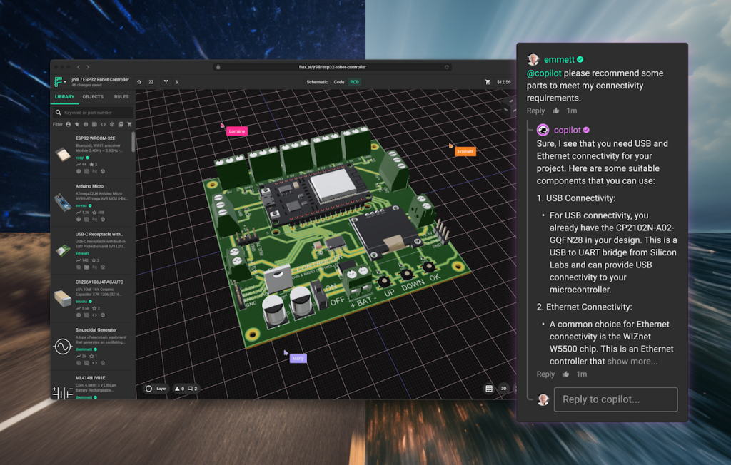
Screenshot of Flux Copilot (Source: Flux.ai)
Let’s start with the fact that Flux Copilot is a web-based tool, which means (a) there’s nothing for you to download and install and (b) you always have access to the latest and greatest version. There’s also a thriving ecosystem of people creating and sharing designs. Users can decide to keep their designs private, share them only within their team, or make them available to the world (well, the flux community).
As Matthias told me, one of the factors that led him to co-found Flux was his frustration in knowing that, when it comes to designing PCBs, “Everyone does everything from scratch every day.” He also notes that common design elements like USB-C connectors and CAN bus terminators aren’t your bread-and-butter IP, so why not share these boring portions of the design with others. Take a USB-C connector as an example. Someone has made a module of this available in the community library. When you pull this module into your schematic view, you see a symbol. When you change to the PCB (layout) view, you see the connector along with any ancillary components (resistors, capacitors), wiring, and silkscreen.
When I asked Matthias as to the number of components, modules, and entire designs in the library, he replied, “It’s in six figures and it’s growing every day.” You can take any of these elements and bring them directly into your design, or you can fork them and change them and then use them and share them as you wish.
So far, so good. It’s at this point that I can imagine you saying something along the lines of, “So, just another schematic and layout tool, huh?” Oh, ye of little faith. Would I be waffling on about this if that were all there was to it? “No!” I cry, “One thousand times no!”
This is where the Copilot part of Flux Copilot comes into play. Flux Copilot is a Flux-trained large language model (LLM) that lives inside your project and can provide direct feedback to help you design faster, safer, and more complex PCBs. Copilot understands the full context of your project, including your list of components, their connections, and related part datasheets. This allows Copilot to respond with highly relevant information to help you select parts, provide feedback, and act on your schematics to help you move faster.
You can commence with a blank sheet and start asking questions like “@copilot can you recommend a real time clock to use with an Arduino,” for example. Alternatively, if you already have a circuit on the screen, you might ask a question like “@copilot what are R1 and C2 doing in this circuit.”
How about being able to say, “@copilot I want to design a PCB for a medical device that measures heart rate and temperature. Can you give me the list of components I’ll need?”
I don’t know anything about audio design (well, nothing worth knowing). I’ve heard people talk about things like “Class D” audio amplifiers, but I have no clue what this means. I mentioned this while chatting to Matthias and Kerry because we were looking at an audio design at this time. They entered the question, “@copilot how would I pick an appropriate amplifier class for this design?” You can only imagine my surprise when it replied by summarizing the differences between Class A, Class B, Class AB, and Class D amplifiers, including their characteristics, advantages, and disadvantages, cumulating by making a recommendation and providing a list of reference sources. It’s worth noting that all this information can be used as documentation you can associate with the design for others to peruse and ponder.
The one that really blew me away—they saved the best for last—was when they dropped the symbols for a microcontroller and an LCD onto the screen and asked Flux Copilot to wire them together. As fate would have it, I’ve worked with this type of LCD before. There are multiple ways to connect it to an MCU, including I2C (only two pins/wires), SPI (four pins/wires but faster and lower power), or using lots of GPIO pins. Wow! Flux Copilot went off, read the data sheets for both devices, recommended using SPI, and connected everything together, including power and ground.
Matthias says that Flux.ai started in 2019, which is only four years ago as I pen these words. As soon as they had something up and running, they moved to an Open Beta. They formally launched in February 2023, and they already have 20,000+ active users, roughly split as 1/3 hobbyists, 1/3 students, and 1/3 professionals.
All I can say is, “Give me strength!” It’s not enough that they created a tightly integrated schematic and PCB layout package with inbuild simulation capability. The amazing thing is that they’ve equipped this bodacious beauty with a generative AI chatbot that can read 1,000-page data sheets in seconds and then tell you what you want to know (e.g., how many UARTs are there on this device and what are their pin numbers), thereby saving you countless hours of frustration (I speak from experience).
If you wish to learn more, bounce over to Flux.ai and read the “What is Flux?” introduction. Then you can experiment with Flux and Flux Copilot for Free (no download required). If you wish to become a Flux Pro with advanced collaboration features and unlimited private projects, this will cost you…
…wait for it… wait for it…
…an incredibly reasonable $15 per editor (which I guess means user) per month. But wait, there’s more, because you can get a 30% discount by paying yearly. Also, the Pro version is free for students and educators. What’s not to love?
So, enough of my waffling, what say you? Are you as amazed by all of this as I am? And, as always, do you have any thoughts you’d care to share with the rest of us?


This is an outrageously verbose article about a very simple topic. Took five pagefuls to even get to the point.
I don’t need to know author’s life story and how it ties to this amazing invention.
The story here is simple. Peeple design chips. Now co-pilot will help.
Enough waffling indeed.
You say: “The story here is simple.”
And yet, somehow you missed the point of the story. You say: “The story here is simple. Peeple design chips. Now co-pilot will help.”
However, Flux Copilot is nothing to do with designing chips — it’s a tool to help design printed circuit boards (PCBs).
You also say: “Enough waffling indeed.”
But that’s what I do best 🙂
It should be illegal to burn a man that hard.
I only hope my words were not too harsh 🙂
Hey Max, great article, as always! At least, “this lad” found it very entertaining! 🙂 I don’t do PCB design but hopefully Virtuoso will be just as clever one day.
Thanks for the kind words Carel — I think we are going to see this type of technology pop up all over the place — we certainly do live in exciting times 🙂