

I’m pickin’ up good vibrations
She’s giving me the excitations – Good Vibrations, The Beach Boys
I live in a condo. When I drive into my condo, I pass through two gates to get to my parking spaces. Each gate employs a motor to open and close it. When we installed these gates several years ago, they worked great. However, as the years have progressed, the gate mechanisms have started to break down. Sometimes a mechanical linkage fails. Sometimes a spring goes sproing. No matter the cause, when a gate breaks, our choices are to shut the gate and switch it off or leave it open until it can be repaired. If we leave it open, then elements of the urban environment walk into the parking levels and cause trouble. If we leave them closed, people can’t enter or exit the parking levels.
Lately, given parts shortages, it’s taken weeks and months to fix one of these broken gates. Now, imagine that you have a factory and a motor fails. Can you afford to idle the factory for weeks and months until the needed replacement parts arrive?
Probably not.
There are millions of electric motors in continuous operation worldwide. According to one study, 82% of companies surveyed have experienced unplanned downtimes costing as much as $250,000 per hour due to motor-related failures. For companies that have experienced this unplanned downtime, outages cost an average of $2 million. Another study found that 70% of companies did not know when assets were due for maintenance or upgrade work. And elapsed time is not a good indicator to use for planning maintenance. Motors don’t wear down on a schedule. Load, temperature, and frequency of use all play a role in the need for maintenance.
That’s why condition-based monitoring (CbM) is becoming more and more important in industrial settings. Companies can cut this expensive downtime if they invest in sensors and monitoring equipment that can detect the early warning signs of failure before the failure occurs. That’s the premise of a multipart article series from Analog Devices (ADI) titled “How to Choose the Best MEMS Sensor for a Wireless Condition-Based Monitoring System,” which is my source for the study findings cited above. ADI is publishing these CbM articles to sell you on its Voyager wireless CbM modules, which are battery-powered vibration monitoring devices intended for industrial use, but the articles are also very informative.
These ADI Voyager modules use MEMS 3-axis ADXL356 accelerometers to detect vibration, and they feed the accelerometer info into a SmartMESH wireless radio network and on to a central monitoring and processing hub. In the past, low power wireless communication devices have struggled to deal with interference generated from the factory floor. ADI specifically designed the SmartMesh network IP for use in dense clusters where wired-like communications reliability and synchronous monitoring or control is required and sensors are numerous, to support a redundant, well-linked mesh networking scheme.
You bolt, strap, or otherwise fasten these Voyager modules to the piece of equipment you want to monitor, and the sensor data flies through the air and into the processing hub for FFT analysis or pattern recognition using machine learning (ML). If you’ve got vibration-monitoring needs that align with what these modules can do, I commend them to your attention. However, in this article, I’m far more interested in the list of things that can go wrong with motors and how you can detect these faults, as discussed in the ADI technical articles.
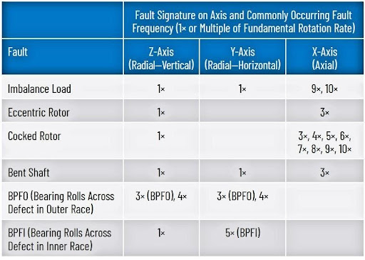
Here are some of the listed motor faults that can occur:
Imbalance and Misalignment
Imbalance and misalignment can produce similar vibrational fault signatures and often surface from the same FFT analysis. An uneven mass distribution around the motor’s center of gravity can cause the motor’s rotor to vibrate, which puts extra strain on the motor bearings and leads to accelerated wear. Eventually, the bearings will fail and the factory, or at least a production line in the factory, will go down. The imbalance might be caused by an improperly balanced motor, or it could be caused by a physical shift in the motor’s rotor windings.
Rotor misalignment occurs when the rotor, the driven shaft, or the associated coupling element is not centered. The misalignment can be angular, parallel, or both. The most common vibration resulting from misalignment occurs at the motor’s rotational frequency but can also appear at twice that frequency. It’s not just the drive components that can become unbalanced. Loads also become unbalanced.
Cocked Rotor
If a motor’s rotor ceases to be mounted in the same position within the motor’s body as when the rotor was balanced, it’s said to be cocked. This can happen because a bearing shifts, or it can be as simple as a setscrew that was tightened out of order after motor maintenance. For whatever the reason, the cocked rotor can create a complex vibrational pattern with a large increase in the vibration at the motor’s rotational rate and an increase in axial vibrational amplitude at 3x, 4x, 5×, 6×, 7×, 8×, 9×, and 10× the rotational rate.
Eccentric Rotor
Motor rotor eccentricity occurs when the air gap between the motor’s stator and rotor becomes unequal, causing an imbalanced magnetic field. The eccentricity might be caused by inaccurate positioning of the rotor with respect to the stator, bearing wear, stator core movement, or shaft deflection. Rotor eccentricity can surface as a large increase in the first vibrational harmonic and a large increase at 3x the rotational rate in the axial direction.
Bent Shaft
The vibrational signature for a bent motor shaft shows a large increase at the motor’s rotational rate in both the radial (z) and (y) directions, and a large increase at 3x that rate in the axial direction. An additional vibrational peak in the y direction at the motor’s rotational frequency helps to differentiate between a bent shaft and an eccentric rotor.
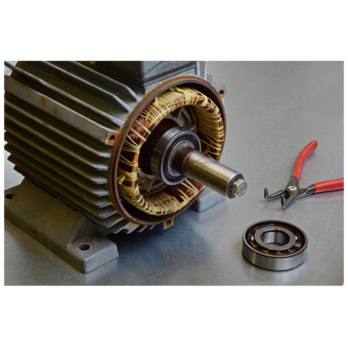
Bearing Defects
Bearing defects have several fundamental classifications. Ball pass frequency inner (BPFI) and ball pass frequency outer (BPFO) signatures appear when rolling elements of the bearing (balls or rollers) roll across a defect in the inner or outer bearing ring, respectively. These two types of bearing faults will produce different vibrational signatures and can therefore be separately diagnosed from these signatures. Because each motor bearing incorporates multiple rollers or balls, the vibrational frequencies of bearing-related defects occur at multiples of the motor’s rotational frequency.
Part 2 of the ADI CbM article series has this handy motor failure diagnostic chart:
I think you’ll agree, industrial motors seem to have many different failure mechanisms, and the consequences of such a failure are expensive. Increasingly, I’d expect more of these motor applications to be instrumented. Whether it’s by MEMS-based sensors like ADI’s Voyager modules or by some other sort of sensor technology, I really can’t say. However, I’m confident that some sort of increased monitoring capability, enabled by new IIoT sensor technologies, is assured a very bright industrial future. The economics demand it.
References:
- Chris Murphy and Richard Anslow, How to Choose the Best MEMS Sensor for a Wireless Condition-Based Monitoring System—Part 1
2. Chris Murphy and Richard Anslow, How to Choose the Best MEMS Sensor for a Wireless Condition-Based Monitoring System—Part 2: How to Detect Mechanical Faults


