

Earlier this week we looked at one of the most useful ways to leverage virtual memory. But there are other reasons for cracking open your chip’s MMU to see what secrets it holds. One is demand paging and the other page-level protection. Both features are built in to every x86 processor, as well as most other CPUs like ARM and RISC-V.
Best of all, these virtual memory techniques aren’t mutually exclusive. You can implement address translation and demand paging and protection if you want to. All it takes is some code, some patience, and some hard decisions about what programs you deem worthy of execution.
First, a recap of why we even have a page directory and page tables at all. Ideally, you could translate every conceivable address to some other arbitrary address, but how would you go about it? Would you have a register somewhere that says, “address 0x00000000 gets translated to address 0x12345678,” and then another one for address 0x00000001, and another for 0x00000002, and so on until you reach 0xFFFFFFFF? That’s nuts, and it would take over 4 billion entries to store each individual translation.
Instead, CPU designers took mercy on us and broke up the address map into manageable 4KB chunks. Right off the bat, that’s a couple of orders of magnitude simpler and with fewer details to set up. Instead of four billion individual translations, we have “only” about a million. The downside, if you can call it that, is that every address within a 4KB chunk of memory gets translated in a group along with its neighbors. I can live with that.
To make things easier still, that million is broken up into 1024 pieces, further reducing the number of details you have to set up. If you’re really lucky (or clever), you’ll need to set up maybe a half-dozen page directory entries (PDEs) and page table entries (PTEs). By having tables point to tables, you gain the ability to reuse – or ignore – many of those thousands of unneeded table entries.
Another detail that’s specific to the x86: your page directory and each of the page tables have to start on a 4KB address boundary. Not a big problem. But – and here’s the fun part – they can be absolutely anywhere in your system’s physical address space. There’s no requirement to put page tables near their parent page directory, or to have either of them near your other x86 data structures, like the GDT, LDT, or IDT. You can scatter page tables all over the place if you want to, or have some in ROM and some in RAM. Go nuts.
The idea behind demand paging is to make your system look like it has more memory than it really does. Everybody wants more memory, but DRAM is expensive. So you lie. You tell your programs – even the operating system – that you’ve got way more memory than you really do. And, surprise, everything still runs great. The only difference you may notice is speed.
Demand paging uses the same two-tiered system of tables we saw before. In fact, they’re the same tables. We just glossed over some of the details before. In the x86 world, every PDE and PTE includes one “Present” bit that tells the CPU whether the item it points to is physically present or not. A PDE’s Present bit says the page table it points to is really there; a PTE’s Present bit says the 4KB chunk of physical memory it points to is really there. If both bits are set, everything’s fine, but if either one is marked not present, the processor generates a page fault (exception 14).
You should mark as “present” any 4KB blocks of memory that really are present in your system. But you can also create page table entries for memory you’ll never have; just be sure to mark them “not present.” Any time a program tries to access one of those not-present areas, the processor will stop what it’s doing and jump to the page fault handler. Then it gets complicated.
Fortunately, the processor will load a status register with some hints about what caused the fault. In our case, it’s because the Present bit wasn’t set in the PDE or the PTE. Your job is to figure out exactly which 4KB address range the program was trying to access and then “insert” some memory into that address space to make the program happy. Obviously, you can’t unsolder memory chips or change the hardware address mapping in your system, but you can make it look like you did. All you have to do is choose an area of memory that you want to temporarily use as a stand-in, and then change its logical-to-physical address mapping to make it appear in the desired location. The amount of memory hasn’t changed, and the physical address of that memory hasn’t changed. You’ve just reused it and altered its apparent location.
This is trickier than it sounds, as you might expect. How do you pick an area of memory to deallocate? What do you do with its contents? What happens to the program that was interrupted?
Your criteria for choosing the memory “victim” are up to you. One easy way is to scan for the least recently used area of memory, but how do you do that? Fortunately, your own page tables might tell you.
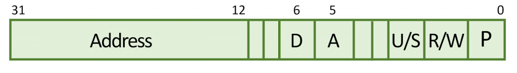
Here’s a simplified diagram of an x86 processor’s PDE and PTE format. The “Present” bit is at position 0, while bit 5 is the “Accessed” and bit 6 is the “Dirty” bit. (Your processor might be a bit different.) After you set up your page directory and page tables, the processor will read them and write to them. Specifically, it will set the Accessed bit any time it accesses the page of memory (or the page table) that it references. This is how you know it’s been used. Or, more accurately, it’s how you know it hasn’t been used. If that bit is still 0, this entry has never been used since the last processor restart, so it’s probably a good candidate for swapping out.
Your next step is to save whatever contents this block of memory held – if you even need to. If it’s mapping a ROM, there’s no need to store a copy of it. If it’s RAM but hasn’t been updated, you still might not need to squirrel away a copy. It’s only if the RAM has changed since you last checked that you’ll need to preserve it, and that’s where the Dirty bit comes in. Your processor sets this bit whenever it writes to this block of memory. It’s never changed on a read, only on writes. Presumably, you’ll want to preserve its contents, so you’ll have to copy it off to a hard disk, SSD, flash memory, or whatever you’ve got.
Once that’s done, you’ll want to update that block’s PTE to mark it “not present.” After all, you just took it out of service, right? Next, you’ll update the PTE for the requested block of memory – the one that caused the fault – and change its physical address to the address of the block you just swapped out. Finally, mark that block as “present” and exit the page fault handler.
If all goes well, the processor will resume from where it left off, and the offending program will retry its memory access. Except this time it will succeed, because you’ve cleverly re-mapped your memory to make it appear that it was there all along. The program won’t know the difference, and the only observable side effect will be the time it took to copy the memory to nonvolatile storage and fiddle with the page tables.
Windows, Linux, and most other operating systems do demand paging all the time. That’s why they reserve an area of the hard disk as “swap space” and why you can often hear the disk thrashing under heavy usage. Swap space is where the OS dumps data it deemed insufficiently worthy to keep in memory. The bigger the swap space, the more blocks of RAM it can keep unmapped at once, and the larger your “virtual” memory space will appear. It’s virtually the same as having more memory!


