


The amount of hardware in orbit for GNSS (Global Navigation Satellite System) navigation is big and getting bigger. The US GPS and Russian GLONASS satellite constellations are already complete. GPS originally consisted of 24 satellites flying in six orbital planes. Each plane had four slots with one operational satellite per slot. In 2011, the US Air Force expanded the constellation and added three satellites for a total of 27 operational slots. This expansion improved GPS-based positioning accuracy in most of the world. As of August 10, 2018, there were a total of 31 operational satellites in the GPS constellation, not including on-orbit spares.
The Russian GLONASS system consists of a network of at least 24 satellites, so its worldwide coverage isn’t as good as GPS. However, GLONASS and GPS operate at different frequencies, so you can get even better positioning accuracy if you take advantage of all 55 satellites in the combined GPS/GLONASS network.
In addition to GPS and GLONASS, the EU and China are also close to finishing their own GNSS systems. The EU’s Galileo GNSS launched in phases. The first four satellites were launched between October, 2011 and October, 2012. Eighteen satellites were launched in the next phase from August, 2014 through December, 2017. The Galileo constellation should be complete by the year 2020.
China is now building its BeiDou-2 GNSS after having decommissioned its original, much smaller BeiDou-1 system. BeiDou-2 became operational with limited coverage in December 2011 using a partial constellation of 10 satellites, and China has been offering navigation services to customers in the Asia-Pacific region since December, 2012. China started building its third-generation BeiDou-3 system in March, 2015, and, as of January 2018, nine BeiDou-3 satellites have been launched. The BeiDou-3 constellation will eventually consist of 35 satellites, and completion of the BeiDou-3 constellation is expected by 2020.
All four of these GNSS systems work in a similar manner, starting with an accurate position fix for each satellite in each GNSS constellation. These satellites are in non-geostationary orbit. That means their position is always changing. Every GNSS receiver keeps an electronic almanac (also called an ephemeris) that provides the expected location for each satellite in a GNSS constellation at any given time—and time is especially important here. Each GNSS satellite keeps time with an atomic clock, and all the satellites’ atomic clocks are synchronized. Each GNSS satellite transmits a signal that encodes the precise time. The GNSS receiver has a less accurate clock.
The GNSS receiver needs to receive these time-coded signals from at least four satellites to give a 3D position fix (latitude, longitude, and altitude) on or above the Earth’s surface. Due to speed-of-light consideration, the time signals will all arrive at slightly different times because the satellites will all be at different distances to the receiver. The GNSS receiver can determine its distance from each satellite by using this time differential and the known positions of the satellites at a specific time. It then solves the multidimensional problem of fitting all the time delays to precisely determine its own position using the 4D equivalent of triangulation (quadrangulation?).
You can track more satellites in multiple constellations to improve the computed position accuracy, but the dimensionality of the position computation gets larger and more complicated. STMicroelectronics conducted positioning accuracy simulation tests back in 2011 and found that, in the urban canyons of Milan, with buildings frequently blocking GNSS signals, the average number of satellites visible in the sky nearly doubled when tracking both GPS and GLONASS constellations, compared to the number when tracking GPS satellites alone.
The simulated GNSS receiver was unable to see enough satellites to compute a position fix for 380 minutes during a 24-hour test period when tracking only GPS satellites. That number dropped to zero (meaning there was 100% satellite availability to compute a navigation fix) when tracking both GPS and GLONASS satellites. As a result, average positioning accuracy improved 60% when tracking satellites in both the GPS and GLONASS constellations.
That’s the simplistic explanation, which assumes that the speed of light is constant. It is, in a vacuum. It’s not on the Earth, because the planet is enveloped in an atmosphere that slightly slows the radio signals beamed from the GNSS satellites, and the amount of signal delay varies depending on atmospheric conditions.
Secondary SBAS (Satellite-Based Augmentation Systems) services provide information that allows suitably equipped GNSS receivers to make position corrections based on atmospheric conditions. SBAS services are operated by different national authorities covering North America (WAAS), Russia (SDCM), Europe (EGNOS), China (BDSBAS), Japan (MSAS), and India (GAGAN). The SBAS corrections make the fix more accurate and the position calculations more complex.
Of course, none of the above includes the description of the RF signal correlation required to find all of these satellite signals and decode them so that multiple satellites can be tracked in real time. There’s also another RF component to receiving these signals. GPS satellites orbit at an altitude of approximately 20 kM and transmit with all of 32.6 watts of power. After traveling through the Earth’s atmosphere, the signal strength is down around -160 dBm, so analog receiver design is challenging as well.
Which is to say that, unless GNSS receiver design isn’t your full time job, you might want to use an off-the-shelf design solution if you still need to add navigation capabilities to your system. Hook up an antenna and power and then get a position fix out.
Such solutions exist. For example, STMicroelectronics now offers a 3rd-generation Teseo III chipset that incorporates all of the analog and digital circuitry and processors needed to receive, decode, and correlate signals from the various GNSS satellites and to compute a position fix from them. Here’s a block diagram of STMicro’s Teseo III chipset:
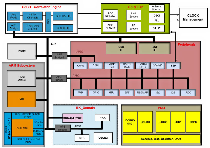
The green box in the diagram contains the analog RF receiver circuitry. The white box contains a baseband processor and correlation engine needed to isolate the transmissions from the various GNSS satellites. This block implements 48 tracking channels and two fast-acquisition channels. These channels can handle incoming signals from the GPS, GLONASS, Galileo, and BeiDou GNSS constellations and can track multiple satellites from multiple constellations simultaneously. The rest of the Teseo III chipset looks like a typical processor-based SoC.
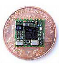
Now if you’re designing a high-volume system, then the chip version of the Teseo III GNSS receiver might be just the ticket. But if you’re designing a low-volume system or you’re not quite up to the rigors of RF design, STMicroelectronics has taken the Teseo III chipset, combined it with some additional components, and has built the Teseo-LIV3F module. This solderable module incorporates the Teseo3 chipset, a 26 MHz TCXO (temperature compensated crystal oscillator), a 32 kHz real-time clock crystal, 2 Mbytes of Flash memory, and assorted passive devices, yet it measures a tiny 9.7 x 10.1 mm and sits very comfortably on a US penny with plenty of room to spare.
Here’s how you hook it up:
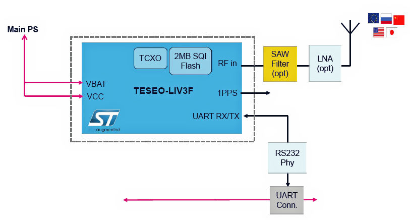
As promised, you connect power to the module and an antenna (with an optional SAW filter if you’ve got a noisy digital environment), and the Teseo-LIV3F module will output a position fix through its UART and I2C interfaces using the standard, ASCII-based NMEA (National Marine Electronics Association) 0183 messaging protocol.
In addition, because the Teseo-LIV3F module incorporates an on-chip, 32-bit, Arm 946 processor and Flash memory, it’s shipped with some prebuilt applications on board including:
Datalogging: Saves latitude, longitude, and altitude to the Flash memory for retrieval by host processor.
Geofencing: Notifies the host processor when latitude/longitude is close to a defined circle.
Odometer: Computes distance travelled from position and velocity data.
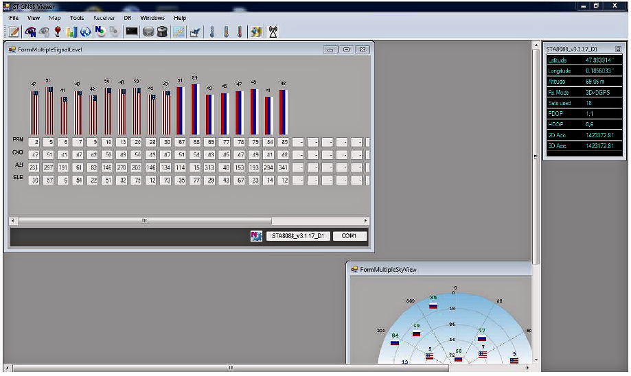
Finally, STMicro supports the Teseo-LIV3F module with the PC-hosted Teseo Suite, a software tool that lets you play with the module’s features. Here’s a screen shot of the software in operation, with multiple open windows showing the satellite tracking channels picking up eighteen GPS and SLONASS satellites (upper left) and mapping them in the sky using the Teseo III ephemeris (lower right).
Oh, and one more thing. Knowing latitude, longitude, and altitude is pretty useful, but knowing where you are on a map is better. So, on September 5, STMicroelectronics and TomTom announced a package of development tools for STMicro’s STM32 Open Development Environment that use TomTom’s Maps APIs for location, tracking, and mapping services.
You may know TomTom for its handheld and automotive GPS products, but the company has morphed into a global mapping information supplier. Its global mapping database, built from 25 years of data gathering, includes navigable maps covering 145 countries in 33 territories with more than 55 million kilometers of navigable roads. These maps are layered to include roads, addresses, traffic signs, points of interest, and 3D representations.
Pretty handy stuff when whatever you’re developing needs to know where it is, where it wants to go, and how to navigate there.


