


Coventor released its most recent version of their SEMulator3D tool not long ago. Just as a refresher, this is the tool that lets process engineers model, analyze, and visualize the impact of a semiconductor process. If you’ve seen nothing else about them, you might have seen animated movies of a process building itself up layer by layer in a conference presentation here or there.
They’ve enumerated five big changes in this last release, along with lots of little fixes or adds. I learned about them in conversation with Coventor CTO Dr. David Fried at the SPIE Advanced Litho conference. We’re going to focus on the big deals and let you discover the little ones as fits your needs.
Going on a Ben – er – Render
The first thing they’ve done is to revamp their rendering engine. This is, of course, critical for their popular visualization tool. While the new engine has improved their look overall, including the fixing of some rendering artifacts, this effort was more about dealing with large models that were taking too long to render.
The poster child for such a model would be a 3D-NAND stack. Depending on whom you’re talking to, you can have 32 layers in the NAND stack – or 64 or more. If that weren’t enough, the people using this tool may be working on early-stage memories that you and I will not have heard of yet. So who knows how many layers they’re working with? And that’s just the 3D-NAND stuff – it doesn’t include all the “normal” layers.
Models like this were bogging the older rendering engine down. The new engine speeds this up – while at the same time reducing the amount of data required to feed the engine. In other words, you can create and visualize a model with less data than was required before, which speeds up the modeling process.
Analyze This
Next come changes to the optimization engine. And there are a couple of aspects to this. Let’s start with the namesake activity of this engine: optimization. Dr. Fried describes two kinds: direct and indirect.
You can perhaps think of direct optimization as “construct by correction.” In other words, given known results and a known process, repeatedly tweak process parameters in a manner that lets the results converge to agreement with the measured data. This capability is still in development.
Indirect optimization can more readily be thought of as reverse engineering: given known results and a known process, can you back that into an accurate model? This is what’s been released in 7.0.
This is closely related to another new capability: calibration. Given an existing model, the tool can modify the parameters to bring the model results into agreement with measured results. Of course, the modified model will be accurate only within a particular range – and you can enter the range of interest. This means that the model might not be accurate outside the range. But, assuming that the range is correctly specified, who cares? All that would do would be to complicate the model for the sake of things the model would never realistically be asked to do.
RC Netlist
No, that’s not a remote-control netlist. It’s the model of parasitic resistances and capacitances used for electrical and timing simulation – particularly in SPICE (since Coventor’s tools don’t work at that level).
First of all, these netlists can now be formatted for SPICE. More substantially, you can also break the RC netlists up – because they’re not lumped. Now… that word caused me a bit of minor confusion, since, in my history, “lumped” was an alternative to “distributed” – the latter applying for longer lines where wave behavior must be considered.
In this case, however, “lumped” refers to an RC network that dumps all the R into one resistor and all the C into one capacitor. The new methodology allows multiple Rs and Cs. Cleaving the model means separating out the Rs and Cs so that the subnetworks themselves work.
What a Mesh You’ve Made!
Penultimate in the big-change pantheon is an addition to the kinds of meshes that SEMulator3D can put out for use by solver engines using finite-element and related techniques. The question here deals with how the meshes are created.
Starting with a random surface or volume, you can break it into triangles (for two dimensions) or tetrahedrons (for three dimensions). You have additional constraints when you come to the physical edge of the volume, since it’s unlikely that the edge would magically happen to align with the place where a triangle or tetrahedron edge would ideally be placed.
As an aside, this issue of what the shape is called for each dimensionality is simplified by referring to the shape generically as a simplex. So the 2D simplex is a triangle; for 3D it’s a tetrahedron. And there’s a tetrahedron analog in 4D, and so on.
So here’s the thing: there are many ways to create these meshes; which ones work best? What’s new in this SEMulator3D release is the ability to create so-called Delauney meshes, which can afford a higher-quality mesh that works better for interpolation.
I had to poke around a little to find out what makes Delauney meshes different. We’ll use 2D as an example since it’s easier to visualize. The idea is that the vertices of any triangle can reside on a circle – referred to as a circumcircle. So you have three points on the circle itself, and no additional points should reside within the circumcircle, as indicated in the drawing below. You may have choices as to how to create the triangles within that circle; the approach favors the choice that maximizes the smallest triangle angles.
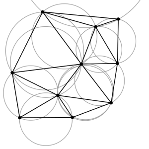
(Image credit: By Gjacquenot – Own work, File:Delaunay circumcircles.png (Nü es), CC BY-SA 3.0, https://commons.wikimedia.org/w/index.php?curid=30370476)
Dealing with Drift and Diffusion
The last of the Big Things is described by Coventor as a first: a drift/diffusion simulator. Let’s break this down. Drift refers to movement of charged entities under the influence of voltage; diffusion refers to similar movement where the cause is a concentration gradient. In either case, you have particles of some sort that are moving, and you might reasonably want to know how they’re going to move.
You can do this today within the TCAD realm. But that typically involves individual devices modeled using ideal geometries – in some cases, requiring that you simplify the structure to make the problem solvable.
The big challenge comes when trying to move the model from one tool to another. This often involves remeshing for the new tool – and TCAD solvers are apparently pretty finicky about their meshes (a situation helped by Delauney meshes). Overall, they see this migration task as something a device engineer might be comfortable doing.
But Coventor is less involved in individual device design and more involved in process integration. Process and integration engineers are not likely to be as comfortable with these tasks as a device engineer would be. This is why Coventor has now added this capability to SEMulator3D. Engineers can now simulate individual devices, getting I/V curves – solved quickly to first-order accuracy.
This can help with sensitivity analysis, particularly when a process change is proposed. One can quickly get a rough picture of how that change will affect individual devices.
This, in particular, would appear to approach impingement on TCAD tools. But Dr. Fried suggests that this is complementary to what the TCAD folks do. The engineers using TCAD tools are, most often, not the same as the ones who use the Coventor tools.
For the process and integration engineers that use Coventor, this is a newer problem. In the past, how to build a device was pretty obvious; tuning performance was the goal. But today, with the crazy new ideas keeping Moore’s Law alive, how to build something isn’t always obvious. So the process and integration guys have to pay more attention to this – at least to get the basic process down. Final tuning then becomes secondary to the fundamental “how do you expect me to build that?” question.
More info:


What do you think about what Coventor has added to SEMulator3D?