


The upshot: Cadence’s Celsius tool provides thermal analysis in tandem with Voltus and Innovus (for chips) and Allegro (for packages and boards).
Temperature has always mattered. But long gone are the days when a chipmaker could blithely declare that they tested their chips over all temps and that they meet the spec. Our chips are now way too complex for such simple treatment, and we also have to play closer to the edge of what’s thermally acceptable, so we’re going for every advantage we can eke out.
We may drive our chips hard in one mode while backing them off in another mode. It’s not just about temperature; it’s also about power and energy usage – especially for battery-powered chips. So the interplay between power and temperature is really important.
Of course, power and temperature also aren’t constant across a chip or board. There are hot spots and cool spots, which is fine – as long as the hot spots aren’t too hot. But that means that we’re not just looking at one single temperature for a chip; we’re looking at different temps at different spots. We now have location as a variable.
At the same time, the boundaries between chip and board have fuzzed out. More and more, we’re having to consider packages and boards as extensions of chips: signals go from the start of a board trace into and through a package and onto a chip. Previously considered to be three different wires (the board trace, the package trace, and the chip wire), we now need to recognize them as one long wire.
All of which is a long way of saying that we need to verify power and temperature characteristics together at the chip, package, and board level. And we need to do so in a way that reflects the many operating modes of a chip or a board.
Which brings us to Cadence’s release of Celsius, their new thermal analysis engine. It can work with Voltus at the chip level and Allegro at the package and board level. It can also work with Virtuoso for custom layout-driven optimization, and it’s integrated with Innovus. They claim that it’s the first of its kind electrical/thermal analysis solution, giving 3D thermal mapping. One of the key benefits of this release is computing scalability that allows for distributed computation and adaptive meshing to speed things up.
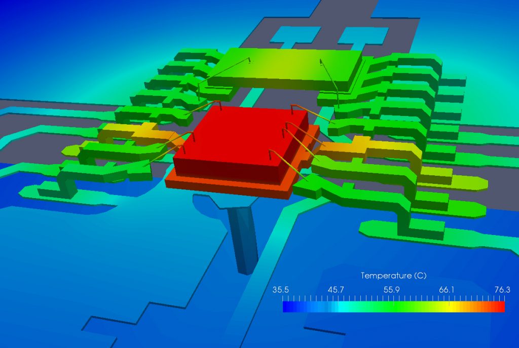
(Image courtesy Cadence.)
Two elements of this verification capability that Cadence points to are co-simulation and analysis of transients. But, in this realm, those words may not mean when you’re used to them meaning. So it’s worth a few minutes digging into the context here.
The System Context
When I think of “co-simulation,” I picture two (or more) simulation engines exchanging on-the-fly information via FLI or PLI or some such mechanism. I guess that’s from my chip background. From my discussion with Cadence, I’m finding that, for system folks, the term refers more to multi-physics simulation that may not be concurrent. So here we’re not talking about electrical and thermal being simulated at the same time, but rather about electrical power analysis completing and sending results to thermal, which completes and can then send its results back to electrical – if desired to keep the loop going (and assuming it converges – more on that in a minute).
Measuring transients also means to me that you’ll watch after some change to see how the system responds and settles into the new steady-state. Electrically, we might be looking for over- and undershoot. Temperature changes also have a trajectory, although it can evolve over a millisecond timescale rather than a nanosecond one – a million times slower.
So transient analysis certainly wouldn’t involve watching how a chip or board responds thermally to a particular set of signals making a big change. What’s more relevant here is a mode change – where large parts of a circuit turn on or off and then remain in that mode for long enough for the temperature to settle into a new state.
When Cadence talks about handling transients, it’s not so much about watching the specific dynamics of the thermal transition, and it’s certainly not about watching the response to a specific electrical signal; it’s more about looking at steady-state temperature for each mode. So, what is the right timescale to use here?
How Many Points?
The real determinant has to do with how long it takes to calculate a thermal point. Digital electrical simulation is event-based, but thermal simulation uses finite-element analysis (FEA) for solids and computational fluid dynamics (CFD) for fluid cooling. With FEA, an entire mesh needs to be calculated for every analysis run.
If you were to repeat the analysis for every nanosecond – the tool is even capable of going down to the 0.1-ns granularity level – then it would take far, far too long to cover any relevant system-level timescale, even with Cadence having pulled out all the stops to make the thermal analysis run quickly. “Quick” is a relative thing. Cadence says that running 100 points or so is a reasonable target. So, if you have 100 points to spend, how do you spend them?
The timescale can vary depending on the material heating up. Silicon can heat up or cool down pretty quickly, so analysis along a timescale of 10s of nanoseconds might make sense. Organic board materials, on the other hand, react more slowly, so such a narrow timescale wouldn’t make sense. This, in particular, is where modes might be the better approach.
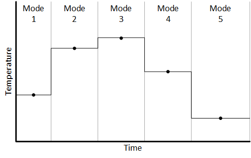
You can look at the specific trajectory of the thermal response as you move from one mode to another, but you’d have to concentrate more points around the mode transition so that you can see the temperature move as it happens.
![]()
It would appear, however, that Cadence’s expectation is that you wouldn’t look so much at the specific transient response, but rather wait for steady-state in each mode.
As compared to a legacy tool, Celsius performs better with an equal number of cores and scales such that an 8-fold increase in the number of cores will give roughly a 5X improvement in performance – not bad, considering the limitations of Amdahl’s Law. Improvement over “legacy” is on the order of 10X with 320 cores.
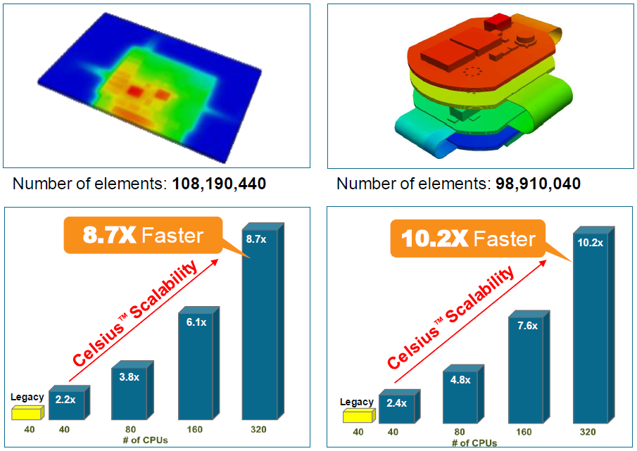
(Image courtesy Cadence.)
A clarification is in order regarding the above data. I asked what “legacy” meant and questioned the performance multiplier between 320 and 40 cores. They said that “legacy” refers to older Cadence tools, not other competitive tools. And the legacy tools couldn’t scale to 320 cores the way the new one can. So it wouldn’t be fair on an apples-to-apples basis to say that the new tool is 10X the speed of the old tool – indeed, comparing 40 to 40, it’s a bit over twice as fast. But, given the ability to scale, it is fair to say that, by leveraging more cores, you can finish the job some 10X faster.
One other consideration: when iterating back and forth between Voltus and Celsius, what if you don’t converge? That might be more than just a simulation artifact: it could signal thermal runaway. In the mode that we’ve discussed so far, it would be up to the designer to notice that things weren’t converging. I asked about this, and they said that they have another option: you can provide Celsius with a “table/library/scaling of the relation between the (leakage) power and temperature.” Celsius can then iterate internally and automatically detect divergence.
More info:
Sourcing credit:
Jerry Zhao, Product Management Director, Multi-Domain System Analysis Business Unit, Cadence
CT Kao, Product Management Director, Multi-Domain System Analysis Business Unit, Cadence


What do you think of Cadence’s new approach to electrical and thermal simulation together?