


A wonderful British ITV television series made in 1979 called “Danger: UXB” depicted the hazardous adventures of a fictitious Royal Engineer tunneling company as it spread out across London to disarm or destroy the thousands of unexploded bombs (UXBs) that penetrated the city’s surface during the Blitz of World War II. I saw the series a year or two later on PBS, where it appeared as a 13-episode “Masterpiece Theater” series. Riveting stuff that I vividly recall watching some 40 years later.
I was reminded of the series, oddly, by a series of brilliant LinkedIn posts by John Dyson, the Business Development Manager for Advance Product Services (APS), a British company specializing in the repair, refurbishment, and replacement of old power supplies. Dyson regularly posts photos of old power supplies. Dead ones. Now you might think there’s nothing notable about old, dead power supplies, but the photos Dyson posts show badly wrecked power supplies that have died catastrophically because of component failure, neglect, and downright abuse.
The failed power supplies depicted in Dyson’s photos reminded me of the “Danger: UXB” TV series because many of the photos showed exploded and badly burned components, and there was one big, recurring theme in the photos: the failure began with an exploding capacitor. So my fevered brain immediately realized that every power supply in operation today contains multiple UXCs – unexploded capacitors. Many capacitors have little timers inside just counting down the seconds until they explode.
What particularly fascinated me about Dyson’s series of posts is that they depict failed power supplies that have given up the ghost after providing decades of reliable service. They died from old age.
Some of the power supplies in Dyson’s posts died from component failures; others died from spikes and surges that sneak through the power main’s protection circuits; some died from aged and embrittled solder joints; and others failed after dust and dirt buildup overwhelmed cooling systems or after water and pollution have eaten away circuit board traces or created conductive paths between them. There are myriad ways for old power supplies to die, it appears, and APS has spent two decades fixing these old supplies and, better for us, chronicling and photographing the failures.
Some months ago, one of Dyson’s posts offered a series of seven free emails that list the top seven reasons that power supplies fail, according to APS’s records. I thought this was an irresistible offer and a brilliant way for APS to build an email marketing list. (Marketers, are you paying attention here?)
I requested the email series and then concatenated the seven APS emails into this article. Here are abbreviated explanations of APS’s top seven failure modes:
1. Electrolytic Capacitor Failure: This is an obvious one for any engineer familiar with aging power supplies. The drying out of wet electrolytic capacitors and related failures are the most common causes of age-related power supply failure. I’ve seen countless photos of smaller electrolytic filter capacitors that have swelled and split their metal vented tops or have spewed their electrolyte guts into a dried, crusty puddle that surrounds the capacitor. I have replaced my share of these dead capacitors, which have failed both mechanically and electrically. According to APS, replacing failed electrolytic capacitors is the number one task for any power supply repair person. The APS email covering electrolytic capacitor failure contains several paragraphs of recommendations for reducing electrolytic capacitor failure, but these components will still dry out and fail after decades of operation.
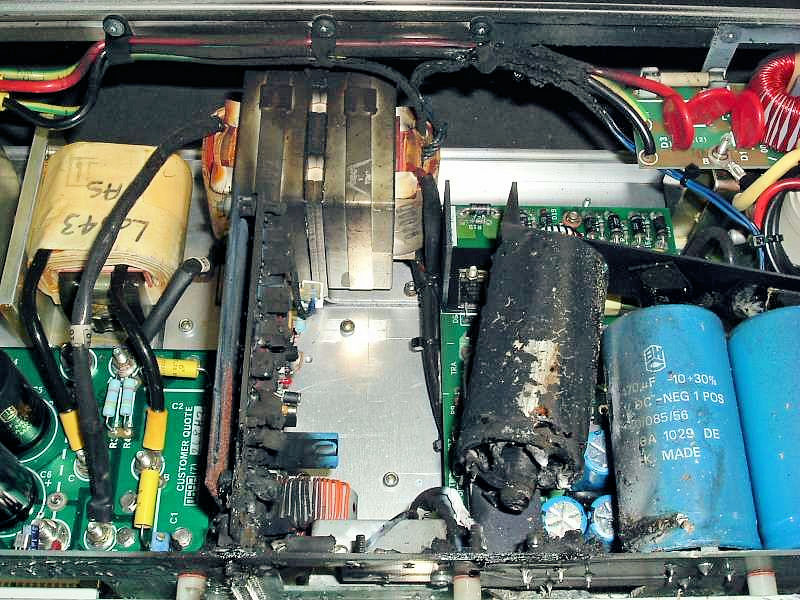
This electrolytic capacitor appears to be fresh off the BBQ. (Image Credit: APS)
- Film Capacitor Failure: Film capacitors are vastly more reliable than electrolytics, but they still can fail over time. Back in the 1970s, many HP divisions, including the one I worked for in Colorado, HP’s Desktop Computer Division, used a line of film capacitors from a company named Rifa for EMI/RFI suppression on the power line. Over decades, the plastic cases of these old capacitors crack simply from aging. The cracks allow water to infiltrate the capacitor. Many collectors of old HP computing gear incorporating these capacitors have discovered that, when they switch on this old equipment for the first time in years or decades, the entrapped water in these old capacitors flashes into steam and violently explodes the capacitor, accompanied by a very loud bang. APS has many photos of similarly exploded capacitors. Metallized polyester snubber caps across switching semiconductors have also been found to fail due to excessive dV/dt. APS recommends that you use polypropylene film capacitors in these applications instead.
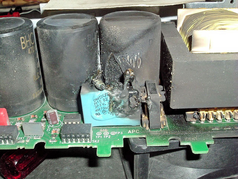
Film capacitors pack a punch when they explode. (Image Credit: APS)
- Failed Surface-Mount, Multilayer Ceramic Capacitors (MLCs): This one surprised me, even though I’m aware of the effects of thermal and mechanical stress effects on SMDs (surface-mount devices). Larger SMD MLCs (specifically the 1812 and 2220 sizes, according to APS) are prone to failure from mechanical stress when mounted on fiberglass or composite circuit boards due to the differential coefficient of thermal expansion between the circuit board and the soldered capacitor. The resulting thermally induced mechanical stress can cause the capacitor to crack and develop an internal short circuit. When those capacitors are used for filtering power supply rails, the power supply goes boom when the capacitor shorts out. APS recommends that you should avoid using large SMD MLCs on circuit boards that experience thermal cycling and never use SMD MLCs in areas where they’ll flex or otherwise distort mechanically. In my experience, nearly all circuit boards designed today experience some thermal cycling and many experience some form of mechanical stress, so proceed with caution here.
- Power MOSFET Failure: According to APS, power semiconductors constitute the component group least prone to failure due to aging, assuming they’re used within their maximum electrical and thermal ratings. However these components account for more than half of all service return failures sent to APS. How can both of these statements be true? Typically, it’s because the semiconductors’ maximum ratings have been exceeded, but not necessarily by design errors. These power semiconductors also fail because of other component failures, spikes or surges, excessive heat, or mechanical stress. Think of failed snubber networks that allow spikes through and cooling fans that have stopped spinning. The APS email describing MOSFET failures in power supplies contains a long list of technical failures observed over the last two decades.
- Optocoupler Aging: Here’s another failure mode that surprised me, even though I’ve known about optocoupler aging for… ages. Optocouplers are commonly used to connect power supply converter circuits across a primary-to-secondary isolation barrier. As these optoelectronic devices age, their current transfer ratio (CTR) gradually falls over time, sometimes to the point of circuit failure. Internally, an optocoupler consists of an infrared LED and an optically coupled phototransistor or photo-detecting IC. Experimental analysis shows that the operating current of the optocoupler’s internal LED is by far the most dominant aging factor. To prolong service life, APS recommends reducing the LED drive current and allowing at least 50 percent margin to account for CTR degradation over time.
- Spikes and Surges: It’s no surprise that power line spikes and surges cause power supply failures. In the UK, where APS is located, lightning strikes cause relatively few energy fluctuations on the power grid. Heavy industry switchgear, large photocopiers and laser printers, HVAC systems, electric motors, and thyristor-driven devices are all notorious for driving spikes and surges into the grid. Even if such transients do not cause instant catastrophic power supply failure, repeated exposure to electrical spikes and surges has a proven degenerative effect on electronic components. APS calls it “transient aging,” and it significantly degrades long-term power supply reliability. If you want to avoid or at least reduce field warranty failures, then it’s not good enough to simply meet spike and noise standards. You must exceed these standards. The APS email dealing with this failure mechanism contains a long list of recommendations.
- Environmental Factors: Cooling fans don’t just suck in air. They also drag dust, lint, dirt, and a long list of airborne pollutants into a power supply, which can cause reliability problems by covering the very components that the fan is supposed to be cooling with a nice insulating blanket of grime. The thermally insulated components will then overheat and fail. In extreme cases, the fan itself clogs and seizes up. Nothing gets cooled. Moisture in the form of water intrusions (storms, pipe bursts, industrial washing) and even condensation also have a role to play in power supply failures. Moisture can combine with grime and pollution to form corrosive compounds that eat circuit board traces. Physical shock and vibration can cause broken solder joints, failed connections, and delaminated circuit board tracks. All of these processes can cause premature power supply failure.
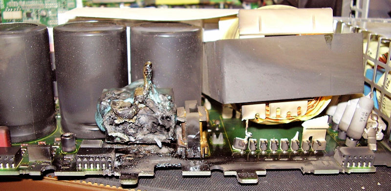
Here’s yet another exploded film capacitor, accompanied by a physically damaged transformer. (Image Credit: APS)
The seven APS “killer” emails contain far more technical detail for each of these deadly failure mechanisms. If you want the full-length descriptions, sign up with APS for the company’s free email series. Highly recommended. You can sign up for these emails here.


