

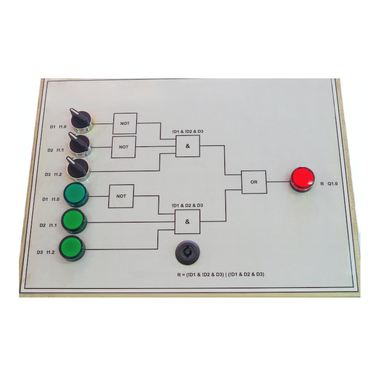
One of the first things we learn in Computer Science 101 is how to reduce and simplify logic truth tables. If you’ve got a bunch of input bits feeding an array of logical OR, AND, and XOR gates, the first thing you want to do is figure out which bits are significant and which are “don’t care.”
With a simple enough circuit and a bit of practice, you can just eyeball it. If a two-input OR has one input true, the other input doesn’t matter. Similarly, a two-input AND with one input tied false doesn’t care about the other input. If the OR feeds the AND, you’ve now got three inputs, so the truth table gets a little more complicated. And so on.
When the circuit’s too complex to just wing it, we build truth tables. (Or, more likely, we let our EDA tools do it for us.) Reducing truth tables means looking for unnecessary or redundant information — for inputs that don’t affect the output. Once in a while, a complex truth table collapses into a much simpler and more elegant one, revealing that a lot of the inputs were unnecessary. Win! Simpler logic, faster circuits, and less hardware.
The trick is in knowing — or at least, in discovering — just how sensitive the circuit is to changes in input. Can a single bit change the output, or does it always require several bits? And if so, which ones?
This seems like a straightforward logic-reduction problem, but it’s not. In fact, quantifying the “sensitivity” of a circuit — its reliance on input changes — has troubled mathematicians and computer scientists for decades.
Knowing for certain that a very complex circuit would be sensitive to changes of a single input would help to design more-robust error-corrections circuits, for example. Conversely, proving that it’s not sensitive to single-bit changes would be helpful, too. We all have our hunches and our tools, but nobody’s been able to absolutely prove sensitivity. Until just recently.
Claire Mathieu, of the French National Center for Scientific Research, in speaking to Quanta magazine, describes the sensitivity problem in an interesting way:
“Imagine that you are filling out a series of yes/no questions on a bank loan application. When you’re done, the banker will score your results and tell you whether you qualify for a loan. This process is a Boolean function: Your answers are the input bits, and the banker’s decision is the output bit.
“If your application gets denied, you might wonder whether you could have changed the outcome by lying on a single question — perhaps, by claiming that you earn more than $50,000 when you really don’t. If that lie would have flipped the outcome, computer scientists say that the Boolean function is “sensitive” to the value of that particular bit. If, say, there are seven different lies you could have told that would have each separately flipped the outcome, then for your loan profile, the sensitivity of the Boolean function is seven.”
Part of the problem with pinning down sensitivity is that it didn’t seem to scale with other measures of Boolean complexity. That bothered mathematicians who were looking for a “grand unified theory” that encompassed everything else we know about binary circuits and Boolean logic. Sensitivity appeared to be an outlier. Maybe.
“This, I would say, probably was the outstanding open question in the study of Boolean functions,” says Rocco Servedio of Columbia University.
Enter Hao Huang, Assistant Professor of Mathematics at Emory University. His approach involved… squares. Not exponential squares, like x2. But actual squares, cubes, and multi-dimensional hypercubes.
The simplest two-input logic gate has four potential input states: 00, 01, 10, and 11. These can be represented by the four corners of a square. If you like, you can think of them as Cartesian coordinates on an X/Y grid, or as latitude and longitude on a map. You can then mark the four corners with a crayon based on whether those inputs produce an output of 1 or 0. If the corner at coordinates 00 produces an output of 1, color that corner blue. If it outputs a 0, color it red. Do the same for the other three corners, and you have a kind of truth table.
If any two adjacent corners (that is, corners connected by a straight line, not diagonally) are the same color, then the circuit is not sensitive to that input. For instance, if corners 00 and 01 are both blue or both red, the output is not sensitive to the second input bit. Simple enough. If two adjacent corners are different colors, the output is sensitive to the bit that changed.
A three-input logic gate (or combination of gates) has eight potential input states, so we need to move from a flat two-dimensional square to a three-dimensional cube with eight corners, but the rules stay the same. Same goes for four inputs: we need a four-dimensional hypercube, and so on. Pretty quickly it becomes complex and hard to imagine.
Huang’s breakthrough came when he decided to apply the Cauchy interlace theorem to the eigenvalues of a subset of the cube’s corners — obviously! As the Quanta article explains, “In this way, he was able to prove that in any collection of more than half the points in an n-dimensional cube, there will be some point that is connected to at least square root of n of the other points — and the sensitivity conjecture instantly followed from this result.”
Specialists Mathieu, Servedio, and others were initially skeptical when they read Huang’s paper, “Induced subgraphs of hypercubes and a proof of the Sensitivity Conjecture.” Like Fermat’s Last Theorem, many had tried and failed before. But realization dawned quickly. “It is just beautiful, like a precious pearl,” wrote Mathieu. “I expect that this fall it will be taught — in a single lecture — in every master’s-level combinatorics course.”
So now, on the one-hundredth anniversary of the truth table, we can finally fill in those missing holes in the squares.


Karnaugh maps!
My CompSci professor in college marked my answer as “wrong”, as I didn’t “do the work on the paper.”
As you mentioned, once you are used to these maps, you can “see” the answers.
I love logic questions, and to me it was a breeze to see on a 2×4 grid what was needed to reduce the logic.
He handed me an alternate question, and I answered it without pencil or paper, so he had no issue with revising my grade.
If you are out there Professor Tymann, thanks again!
I guess this is great news for somebody but do we really need it? I believe that US patent 10,181,003 obviates the need for Boolean or State structures to solve any computation that has a solution. The asynchronous model described by US 10,181,003 synthesizes the parallel model to hardware without these structures and without a clock. Combining Boolean structures with US 10,181,003 does have some advantages though.