

I often think about ancient civilizations. I’m sure you do too. I cogitate and ruminate on all the people who lived, loved, and died, and I’m saddened by the fact that we no longer remember their names. In many cases, we aren’t even aware that their civilizations existed (I base this on the fact we seem to keep on discovering previously unsuspected cultures and empires).
I learn something new every day. For example, I just discovered that, while all Sumerians were Mesopotamians, not all Mesopotamians were Sumerians. It’s obvious when you think about it because some Mesopotamians were members of other empires that existed in the Mesopotamian area at the same time as the Sumerian kingdom. I know, “Duh,” right?
The reason I mention this here is that I love devices used to perform calculations in all their incarnations, starting with the abacus, the Sumerian / Mesopotamian version of which appeared sometime between 2700 and 2300 BC. I’m also intrigued by the people who came up with cunning concepts, like the Scottish mathematician, John Napier, who invented Napier’s Bones in the early 1600s. These were multiplication symbols inscribed on strips of wood or bone. Napier also invented logarithms. In 1621, the English mathematician and clergyman, William Oughtred, used Napier’s logarithms as the basis for the slide rule.
Over time, people started to create mechanical calculators, like Blaise Pascal with his Arithmetic Machine and Gottfried von Leibniz with his Step Reckoner. These early devices evolved into full-up mechanical computers from folks like Charles Babbage and his Analytical Steam Engine (which never actually worked) and Konrad Zuse with his Z1 (which did).
Charles Babbage (Source: Max Maxfield and Alvin Brown)
Eventually, of course, people developed the electronic calculators and computers we’ve grown to know and love today. I, for one, cannot imagine a world without these little beauties. I find it increasingly hard to remember those dark, dismal times when I was forced to walk across a room to control the lights or television, as opposed to simply lounging back in my comfy command chair and saying something like, “Alexa, please turn the television on.”
I find it interesting to note that, while most of my engineering friends are familiar with the history of calculators and computers—at least when painted in broad strokes—many are unfamiliar with the fact that there has historically been a great deal of fascination with logic in general. This fascination was initially expressed in the form of logic diagrams, and later in the construction of special-purpose machines for manipulating logical expressions and representations.
I was just ambling past one of the bookshelves in my office when I spotted the book Logic Machines and Diagrams by Martin Gardner, who—among many other things—was famous for his Mathematical Games columns, which appeared in Scientific American for 25 years. I wrote about this in Bebop Bytes Back: An Unconventional Guide to Computers, which I co-authored with my friend, Alvin Brown. I just re-read what we wrote, and I decided to share it here on the off chance you would find it as interesting as does your humble narrator (as you know, I pride myself on my humility—you’ll have to go a long way to find someone humbler than me). So, sit back and make yourself comfortable because here we go…
The Tree of Porphyry
Diagrams used to represent logical concepts have been around in one form or another for a very long time. For example, Aristotle (384-322 BC) was certainly familiar with the idea of using a stylized tree figure to represent the relationships between (and successive sub-divisions of) such things as different species. Diagrams of this type, which are known as the Tree of Porphyry, are often to be found in medieval pictures.
John Venn and his Venn Diagrams
Following the Tree of Porphyry, there seems to have been a dearth of activity on the logic diagram front until 1761, when the brilliant Swiss mathematician Leonhard Euler introduced a geometric system that could generate solutions for problems in class logic. However, Euler’s work in this area didn’t really catch on because it was somewhat awkward to use, and it was eventually supplanted in the 1890s by a more polished scheme proposed by the English logician John Venn (1834-1923). Venn was heavily influenced by the work of the English mathematician George Boole (1815-1864), and his Venn Diagrams very much complemented Boolean algebra.
Venn Diagrams were strongly based on the interrelationships between overlapping circles or ellipses. The first logic diagrams based on squares or rectangles were introduced in 1881 by Allan Marquand (1853-1924). A lecturer in logic and ethics at John Hopkins University, Marquand’s diagrams spurred interest by a number of other contenders, including one offering by an English logician and author, the Reverend Charles Lutwidge Dodgson (1832-1898).
Dodgson’s diagrammatic technique first appeared in his book The Game of Logic, which was published in 1886, but he is better known to us by his pen-name, Lewis Carroll, and as being the author of Alice’s Adventures in Wonderland. Apart from anything else, these rectangular diagrams are of interest to us because they were the forerunners of a more modern form known as Karnaugh Maps. These graphical techniques, which were invented by Maurice Karnaugh in the 1950s, quickly became one of the mainstays of the digital logic designer’s tool chest.
Ramon Lull and his Ars Magna
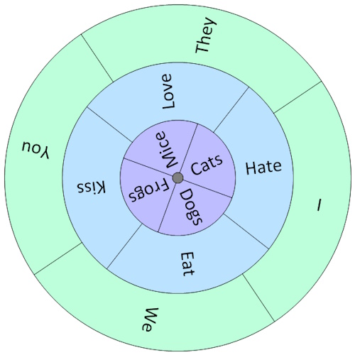
Possibly the first person in the history of formal logic to use a mechanical device to generate (so-called) logical proofs was the Spanish theologian Ramon Lull (1232-1316). In 1274, feeling remorse for having done something naughty, Lull climbed Mount Randa in Majorca in search of spiritual sustenance. After fasting and contemplating his navel for several days, Lull experienced what he believed to be a divine revelation, and he promptly rushed back down the mountain to pen his famous Ars Magna. This magnum opus described several eccentric logical techniques, but the one of which Lull was most proud (and which received the most attention) was based on concentric disks of card, wood, or metal mounted on a central axis.
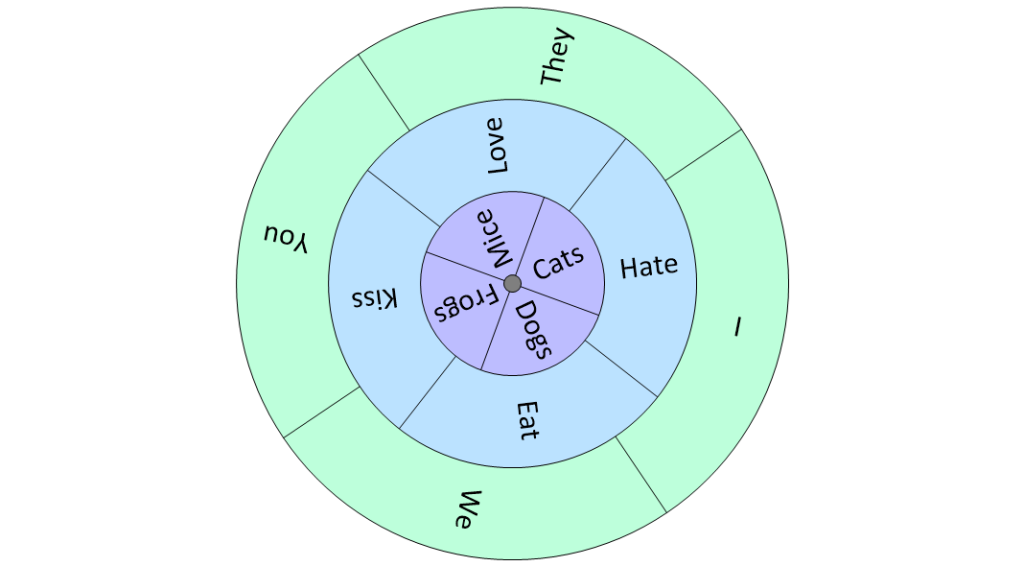
Ramon Lull-type disks (Source: Max Maxfield and Alvin Brown)
Lull’s idea was that each disk should contain a number of different words or symbols that could be combined in different ways by rotating the disks. In the case of our somewhat jocular example above, we can achieve 4 x 4 x 4 = 64 different sentences along the lines of “I love mice,” “You hate cats,” and “They [The French] eat frogs.”
Of course, Lull had a more serious purpose in mind, which was to prove the truth of everything contained within the Bible (he didn’t believe in thinking small). For example, he used his disks to show that “God’s mercy is infinite,” “God’s mercy is mysterious,” “God’s mercy is just,” and so forth.
Lull’s devices were far more complex than our simple example might suggest, with several containing as many as sixteen different words or symbols on each disk. His masterpiece was the Figura Universalis, which consisted of fourteen concentric circles. The mind boggles at the range of combinations that could be generated by this device. Strange as it may seem to us, Lull’s followers (called Lullists) flourished during the late Middle Ages and the Renaissance, and Lullism spread far and wide across Europe.
Why is all of this of interest to us? Well, by some strange quirk of fate, Lull’s work fired the imagination of several characters with whom we are already familiar, such as Gottfried von Leibniz who invented the Step Reckoner. Although Leibniz had little regard for Lull’s work in general, he believed there was a chance it could be extended to apply to formal logic. In a rare flight of fancy, Leibniz conjectured that it might be possible to create a universal algebra that could represent just about everything under the sun, including (but not limited to) moral and metaphysical truths.
In 1666, at the age of 19, Leibniz wrote his Dissertio de Arte Combinatoria, from which comes a famous quote describing the way in which he believed the world could be in the future: “If controversies were to arise,” said Leibniz, “there would be no more need of disputation between two philosophers than between two accountants. For it would suffice to take their pencils in their hands and say to each other: ‘Let us calculate.’”
Jonathan Swift and Gulliver’s Travels
Of course, it’s safe to say that Ramon Lull also has his detractors (which is a rather kind way of saying that many people considered him to be a raving lunatic). In 1726, the Anglo-Irish satirist Jonathan Swift wrote Gulliver’s Travels, which was originally intended as an attack on the hypocrisy of the establishment (including the government, the courts, and the clergy—Swift didn’t like to restrict himself unduly), but which was written so pleasingly that it immediately became a children’s favorite. (On the off chance you were wondering, Swift penned his great work nine years before the billiard cue was invented. Prior to this, players used to strike the balls with a small mace.)
Jonathan Swift (Source: Max Maxfield and Alvin Brown)
Returning to Gulliver’s Travels… In Part III, Chapter 5 of the tale, a professor of Laputa shows Gulliver a machine that generates random sequences of words. This device was based on a 20-foot square frame supporting wires threaded through wooden cubes, where each face of every cube had a piece of paper bearing a word pasted onto it. Students randomly changed the words using forty handles mounted around the frame. The students then examined the cubes, and if three or four adjacent words formed part of a sentence that made any sense, they were immediately written down by scribes. The professor told Gulliver that by means of this technique: “The most ignorant person at a reasonable charge, and with little bodily labor, may write books in philosophy, poetry, law, mathematics, and theology, without the least assistance from genius or study.”
The point is that Swift is believed to have been mocking Lull’s art when he penned this part of his story. (Having said this, computer programs have been used to create random poetry and music …… which makes you wonder what Swift would have written about us.)
In fact, Swift continues to affect us in strange and wondrous ways to this day. When a computer uses multiple bytes to represent a number, there are two main techniques for storing those bytes in memory: either the most-significant byte is stored in the location with the lowest address (in which case we might say it’s stored “big-end-first), or the least-significant byte is stored in the lowest address (in which case we might say it’s stored “little-end-first). Not surprisingly, some computer architects (designers) favor one style while others take the opposite tack.
This didn’t really matter until people became interested in creating heterogeneous computing environments in which multiple diverse machines were connected, at which point many acrimonious arguments ensued. In 1980, a famous paper written by Danny Cohen titled On Holy Wars and a Plea for Peace used the terms “big-endian” and “little-endian” to refer to the two techniques for storing data. These terms, which are still in use today, were derived from that part of Gulliver’s tale whereby two countries go to war over which end of a hard-boiled egg should be eaten first—the little end or the big end!
Lewis Carroll’s Logical Conundrums
Leaping from one subject to another with the agility of a mountain goat, we might also note that Lewis Carroll (who was mentioned in an earlier topic) enjoyed posing logical conundrums in many of his books, such as Alice’s Adventures in Wonderland (1865), Through the Looking-Glass (1872), and The Hunting of the Snark (1876).

Lewis Carroll (Source: Max Maxfield and Alvin Brown)
For example, consider this scene from the Mad Hatter’s tea party in Chapter 7 of Alice’s Adventures in Wonderland:
“Take some more tea,” the March Hare said to Alice, very earnestly.
“I’ve had nothing yet,” Alice replied in an offended tone: “so I can’t take more.”
“You mean you can’t take less,” said the hatter: “it’s very easy to take more than nothing.”
Apropos of nothing at all, the phrase “As mad as a Hatter” comes from the fact that, in ye olden tymes, the manufacturers of men’s top hats used mercury compounds as part of the process. Over time, the mercury accumulated in their bodies causing severe impairment to their mental functions.
And we would have to chastise ourselves soundly if we neglected the scene involving Tweedledum and Tweedledee in Chapter 4 of Through the Looking-Glass:
“I know what you’re thinking about,” said Tweedledum; “but it isn’t so, nohow.”
“Contrariwise,” continued Tweedledee, “if it was so, it might be; and if it were so, it would be; but as it isn’t, it ain’t. That’s logic.”
You must admit, these gems of information aren’t to be found in most of the other things you’ve read today, but I fear we are in danger of wandering off the beaten path (“No,” you cry, “tell me it isn’t so!”).
Charles Stanhope and His Stanhope Demonstrator
The world’s first real logic machine in the sense that it could actually be used to solve formal logic problems—as opposed to Ramon Lull’s, which tended to create more problems than it solved—was invented in the early 1800s by the British scientist and statesman Charles Stanhope (1753-1816).
The third Earl of Stanhope and a man of many talents, he designed a device called the Stanhope Demonstrator, which was a small box with a window in the top along with two different colored slides that the user pushed into slots in the sides. Although this doesn’t sound like much, it was a start (there was more to this device than we can cover here), but Stanhope wouldn’t publish any details and instructed his friends not to say anything about what he was doing. In fact, it wasn’t until around sixty years after his death that the Earl’s notes and one of his devices fell into the hands of the Reverend Robert Harley, who subsequently published an article on the Stanhope Demonstrator in 1879.
William Jevons and His Logic Piano
Working on a somewhat different approach was the British logician and economist William Stanley Jevons (1835-1882), who produced the earliest model of his famous Jevons’ Logic Machine in 1869. This device is notable because it was the first machine that could solve a logical problem faster than that problem could be solved without using the machine!
Jevons was an aficionado of Boolean logic, and his solution was something of a cross between a logical abacus and a piano (in fact it was sometimes referred to as a “Logic Piano”). This device, which was about 3 feet tall, consisted of keys, levers, and pulleys, along with letters that could be either visible or hidden. When the operator pressed keys representing logical operations, the appropriate letters appeared to reveal the result.
Allan Marquand and His Logic Machine
The next real advance in logic machines was made by Allan Marquand, whom we previously met in connection with his work on logic diagrams. In 1881, by means of the ingenious use of rods, levers, and springs, Marquand extended Jevons’ work to produce the Marquand Logic Machine. Like Jevons’ device, Marquand’s machine could handle only four variables, but it was smaller and significantly more intuitive to use. (Following the invention of his logic machine, Marquand abandoned logical pursuits to become a professor of art and archeology at Princeton University.)
Benjamin Burack and his Electrical Logic Machine
Things continued to develop apace. In 1936, the American psychologist Benjamin Burack from Chicago constructed what was probably the world’s first electrical logic machine. Burack’s device used light bulbs to display the logical relationships between a collection of switches, but for some reason he didn’t publish anything about his work until 1949.
In fact, the connection between Boolean algebra and circuits based on switches had been recognized as early as 1886 by an educator called Charles Pierce (1839-1914), but nothing substantial happened in this area until 1937 when a graduate student at MIT, Claude E. Shannon, submitted his master’s degree thesis, A Symbolic Analysis of Relay and Switching Circuits. In this thesis—and in a follow-up paper in 1938—Shannon showed that Boolean algebra offered an ideal technique for representing the logical operations of digital systems. Shannon had realized that the Boolean concepts of false and true could be mapped onto the binary digits 0 and 1, and that both could be easily implemented by means of electronic circuits.
Following Shannon’s paper, a substantial amount of attention was focused on developing electronic logic machines. Unfortunately, interest in special-purpose logic machines waned in the 1940s with the advent of general-purpose computers, which proved to be much more powerful and for which programs could be written to handle myriad tasks… including formal logic.
As usual, we’ve only scraped the surface of a very interesting topic. If you know of any other logical diagrammatic techniques or machines, it would be great if you could share them with the rest of us in the comments below.


And the wiring of the light switches in your home where there are multiple doorways and a switch at each will turn the ceiling light on or off. Each switch has 2 positions, usually up or down or left or right, but no multi position rotaries. The light has one bulb with 2 wires.
Where to start to define the logic diagram of the “light control machine”?
In the case of two such switches, if we say Up = 1 and Down = 0, also that the light being on = 1, then this is a classic XNOR case:
0 0 = 1
0 1 = 0
1 0 = 0
1 1 = 1
I don’t think you can do this easily with more than two such switches.
Single pole double throw (maybe called 3 way switches) are acceptable.
Double pole double throw(maybe called 4 way switches) also ok
two three way switches to turn light on/off at 2 places.
For each additional place wire in a 4-way as many as you want between the 3 ways.
Any electrician knows this … but the logic diagram gets a little tricky, I think.
I’d love to see a logic diagram for say four switches all controlling the same light 🙂
sorry, I did not mean that only 3 way switches are allowed. and yes, it is an exclusive or/nor case.
Hi Max, how about Ron Lavallee and his Flowchart Logic Machine? Or, better known as Flowpro.
Karl’s problem points out why all Programmable Logic Controllers (PLC’s) have transitional inputs.
Hi Ron — Ah, the legendary FlowPro machine — is there anything it cannot do? LOL
I never met a FlowPro … But I am fairly well acquainted with the Roslyn(C#) compiler and its API.
So WHAT? Well instead of the old tattered load, add, store, branch(if/else) it is the chip(CPU) designer’s “Swiss Army knife”. The most recent is the conditional assignment that obsoletes the compare step and “if” for assignments.
Here is an example:
Once upon a time, there was an”All Programmable Planet” and this assignment expression was
submitted by Brian Bailey in the HLS discussion:
A = B + C * D – (E + F)*A
By substituting corresponding decimal values for the terms which happen to have “hex like” names
A = 11 + 12 * 13 – (14 + 15) * 10;
So we compile the expression and use the Syntax Walker to step through the evaluation and out comes -123 as the value assigned to A. (-123 is from memory since I am too lazy to rerun it)
12 * 13 = 156
156 + 11 = 167
14 + 15 = 29
29 * 10 = 290
167 – 290 = -123, yep looks right.
multiply, add, add, multiply, subtract
And I can step thru the evaluation.
Sorry, he compare step is still there, not as a binary expression and variable assignments(they are just hidden in the parenthesis.
Conceptually, in my opinion, no there isn’t, but I am sure doubt remains in others because a mathematical proof of a Flowpro Machine does not exist. Practically, we are showing how to propagate Flowpro Machine flowcharts in an FPGA using auto generated parallel Verilog code. It’s not fully an asynchronous design but close.
“…a mathematical proof of a Flowpro Machine does not exist…”
Why not?
Hi Max, the main reason is that I am not smart enough. I’m just a night school engineer so an empirical proof is the path I use. If you know somebody, send them my way?
A Flowpro Machine is parallel computational waves propagating through substrate. Parallelism is a quality of its own. Karl’s problem, with 100 entrances, would use 100 five block flowcharts to detect switch status change and one flowchart to monitor switch status changes and toggle the light.
Not if you use a sequence/series of exclusive ors (parity tree) to detect odd number of changes. Good catch!
Is there any tool or “whatcha might call it” that uses flow charts for source code input?
Without computer readable source input “yer ded in tha wadder”!
Verilog and that other thing are horrible, BUT! Logic design is about named inputs and outputs which are signals and data busses and the fun part is defining the logic to control the data flow.
And one of the disgusting things about the HDLs that they ignore the problem of connecting signals and busses.
But you say “That’s what FlowPro does!” Wishing you luck because the tools do not “read” flow charts. And you might say “They should” …
And my approach is a simple “natural” syntax that I hope will not make designers barff, but can still be easily parsed to generate source code using a subset of the C# syntax.
Hi Karl, I enjoy answering your questions. Yes, the source code for Flowpro Software and a Flowpro Machine is decision flowcharts which are computer readable. A user is always working with flowcharts and not traditional code. The idea behind Flowpro is that you model your algorithm or application with flowcharts and you’re done, period! We have built a reference design utility that takes multi-flowchart Flowpro Software and translates it to a parallel Verilog file. The Verilog file is an image of the original Flowpro flowcharts. The Verilog file is fully documented and all Verilog signal names are derived on the flowchart so it’s easy to read the Verilog code. The Verilog code is then placed in your FPGA design project, Intel in our case, and compiled and synthesized by the FPGA system. The beauty of this is that from this point on it is standard EDA tools some of which are not necessary with a Flowpro Machine design technique.
Please contact me directly and I will send you some documents showing this process.
This looks like I am talking to myself, but I can’t seem to reply to ronl directly.
A long time ago (BC before computers) flowcharts were sort of a manual GUI.
But books were written in languages which are more concise.(agree?)
Automating from flowcharts to Verilog still leaves me wanting. I want things connected logically and to be able to exercise my design interactively(debug). Verilog still must be simulated in a separate step by a completely different program/simulator. I am a designer/ debugger and am absolutely frustrated by the stupidity of doing place and route and synthesis of an incomplete design and on top of that being left with generating waveforms and having to analyze waveforms manually for debug. Then still on top of that, having to tell the “tool” which inputs are inputs and which outputs are outputs.
It is not intuitively obvious that pouring thru flowcharts and whatever else in in the path to get to:
These are the inputs
These are the results(outputs)
This is how the inputs were processed
This is what the result should be
And while we are here, FSMs are unnecessary and a potential source of errors.
Because the FSM state is defined by the designer/user rather than the actual logic.
The state is determined by the inputs and the sequential combining of internal states with inputs until the final state is reached. (And I have read comments by wanna be designers) “everything happens at once”. HumBug! Things happen at the rate determined by the design and technology. Of course everyone knows that because they cannot wait to buy the new phone.
Have you ever used it to actually design and debug? I just looked for my flowchart template and cannot find it. Oh well, only used it once anyway!
Another thing I have noticed is that thousands of programmers are using compiled languages and there seems to be a new one every few days. Have not seen a live flowchart this century.
Reminds me of my Mom’s sayings about a mother watching a parade and one guy was out of step… The Mother exclaimed “Look! Everybody is out of step but my Johnny!”
But Karl you are thinking about flowcharts as if it were still BC. Automating from flowcharts to Verilog allows true parallel execution of the logic. Interactively debugging a Flowpro application happens in two ways. First, you can run your Flowpro on a CPU and functionally debug using powerful tools for database status and forcing, a snapshot of were all flowcharts are executing and a breakpoint trace of flowchart scans. Secondly, the utility that automates the flowchart to Verilog allows a user to select monitor points on any block on any flowchart. Monitor points are outputs you can use to track the progress of your flowcharts. The Verilog simulation tools, including waveforms, are not needed but I believe a scan chain will fit nicely with flowchart debug.
I urge you to go to our website and download the configurable hardware document and look at the flowchart drawings. Inputs and outputs are plainly identified on the flowchart with labels and mnemonics, I-00, O-00, TC-00 etc.. Following the flowchart logic is straightforward especially with using a hierarchy of Action, Test and Task objects. As for the state machines, a flowchart is not a state machine and I agree they are unnecessary when doing event-based programming.
To your last comment. YES I have! As an example, a 42 station transfer machine at General Motors Powertrain. Approximately 11,000 I/O points including servos running on an IBM 486 PC processing approximately 700 Flowpro flowcharts in under 40 ms. In addition to numerous other projects. Contact me and I’ll send you some.
There were also mechanical analog computers…indeed, some new ones have been built recently. See my post Retrotech–With a Future?
https://chicagoboyz.net/archives/57194.html
I opened my “TTL Data Book” (I still have mine) and found data selectors and multiplexers.
But I don’t have graphics drawing… so I will try to talk thru it.
on the left side a 1 to 2 mux. The current to turn on the light is the “data” input.
on the right side a 2 to 1 demux. The current that turns the light on is the “data” output.
in between are 2 – 2 to 2 mux (4 way switches) — switch down white to white, black to black; switch up white to black, black to white.
power into room black to first switch, white to light.
power to light black from last switch.
Ah, light dawns! 🙂
Wow! Mechanical analog computer … The Mark IA gunfire control computer was my first… It took bearing and elevation inputs from radar and pitch and roll inputs from a gyroscope and computed the elevation and rotation for the gun so the projectile trajectory would intercept the moving or stationary target.
It did this in real time while no digital computer was fast enough….
PS Radar supplied the speed and distance to the target and the speed and bearing of the ship were also inputs.
I’m always impressed with analog computers — especially mechanical analog computers — did you see my Cool Beans Blogs:
Wilberforce Pendulums and Wiffletree Converters
https://www.clivemaxfield.com/coolbeans/wilberforce-pendulums-and-wiffletree-converters/
Spintronics (Mechanical Electronics) Makes Your Head Spin
https://www.clivemaxfield.com/coolbeans/spintronics-mechanical-electronics-makes-your-head-spin/
The Analog Thing (THAT)
https://www.clivemaxfield.com/coolbeans/the-analog-thing-that/
The latter one has a video of some cool mechanical analog computational elements.
So long all. I do not need another step to generate Verilog on top of all the useless steps that the tool chain already requires. If something does not work as expected, I need to get right down to the logic, not to fiddle fart around with synthesis, placement, timing analysis. I am just not interested in how fast it does not work.