

“Beep beep’m beep beep yeah,” – John Lennon and Paul McCartney
While several companies are expending significant resources and large amounts of energy to develop automated driving for passenger vehicles, trucks, and buses here on Earth, a dedicated group of scientists and engineers at JPL (the Jet Propulsion Lab) have been working on a related but significantly different problem: creating autonomous driving capabilities for Mars. Mars rovers are really far away – anywhere from 55 to 400 million kilometers distant depending on where the Earth and Mars are in their orbits. The speed of light is roughly 300,000 kilometers/sec so radio communications require anywhere from three to 22 minutes for the one-way interplanetary trip. Double that for the round trip communications you’d need for remote driving with visual feedback. Obviously, that’s not going to work. There’s no way to drive a Mars rover remotely from Earth in real time because of the long time lag. Some sort of autonomous robot driving capability is mandatory for Mars until Elon Musk sends himself and other humans there to do the driving (presumably in Tesla electric cars).
We probably don’t need to worry about running into other vehicles or hitting pedestrians on Mars. At least, that’s the assumption until we see Mad Max style dune buggies roar over a distant Martian hill. If we do see something like that, we’ll have more problems to deal with than rules of the Martian roads. Speaking of roads, there are a host of terrestrial driving problems – such as understanding lane markings, stop signs, posted speed limits, stop lights, etc. – that have no meaning on the surface of Mars. (“Roads? Where we’re going, we don’t need… roads.”)
The Rover Roll Call
To date, NASA has landed four rovers on Mars with increasing levels of driving autonomy, and a fifth is planned for launch in the near future. The Pathfinder mission launched on December 4, 1996 and carried the first successful Mars rover, the solar-powered Sojourner. Pathfinder safely landed on Mars’s Ares Vallis on July 4, 1997, using a unique airbag landing system that looked like a bag full of soccer balls, and bounced along one of the rockiest portions of the Martian surface until it rolled to a stop.
Two sols (Martian days) after the landing, Sojourner then drove off of the Pathfinder lander and onto the Martian surface. This first successful Mars rover traveled a total distance of just over 100 meters or, appropriately, the approximate length of a soccer pitch, from its Pathfinder lander before communications were lost three months later. It’s likely that a battery failed, possibly from the Martian cold. When the mission ended, Sojourner had exceeded its minimum planned 7-day operating period by 12x and had sent 550 images of the Martian landscape back to Earth.
While the Pathfinder lander used a rad-hard RAD6000 CPU based on the PowerPC architecture, the Sojourner rover’s CPU was a 2MHz 80C85 with 64 Kbytes of memory. (That’s an oh, oh, oh, oh, old 8-bit CPU from the 1970s, if your processor history is a bit thin.) Thus, the Sojourner rover had all of the computing power of the Radio Shack TRS 80 Model 100 portable computer that I purchased back in 1985.
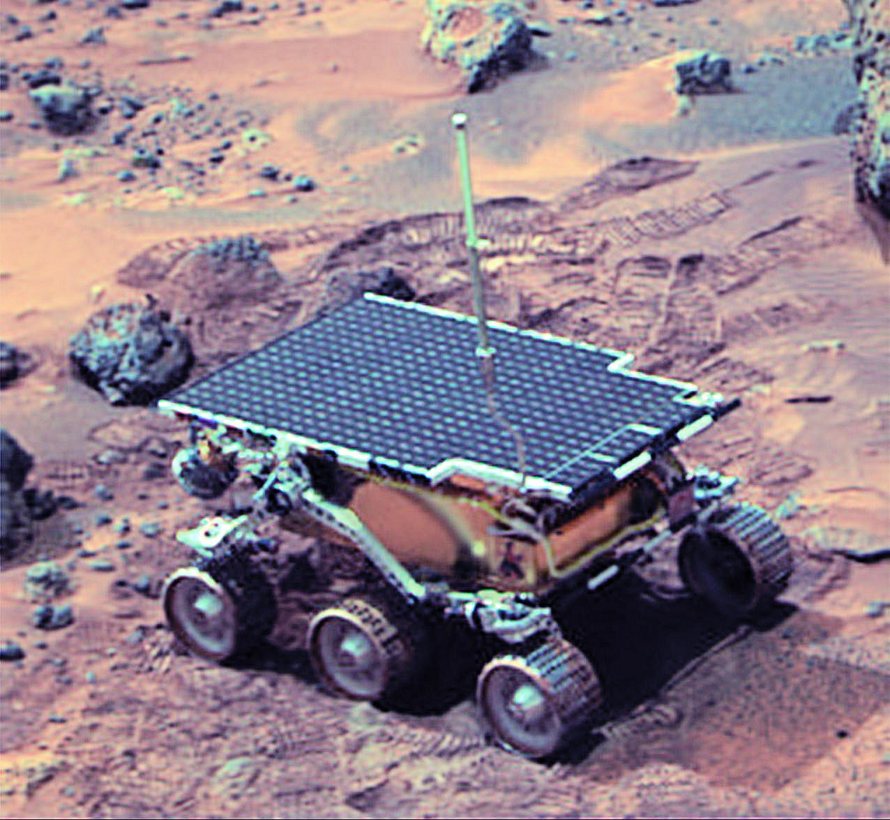
Figure 1: The solar-powered Sojourner rover on Mars. (Image credit: NASA/JPL)
Sojourner’s connection back to Earth was about as tenuous as possible. It communicated with the Pathfinder lander over a 9600-baud RF modem that delivered an effective data rate of just 2600 baud and a theoretical maximum range of about 500 meters – a tight, short, narrow tether. Consequently, autonomy was not high on the Sojourner’s requirements list due to the short range of the RF link, the limited mobility of the rover, and the short mission duration. Sojourner was driven by a very patient human who sat in an Earthbound driver’s seat wearing 3D goggles and gave the rover explicit movement commands. No autonomy there, but it sure would have helped.
Spirit and Opportunity
The next two planetary rovers to successfully arrive on Mars were Spirit and Opportunity, part of the Mars Exploration Rovers (MER) mission. Like Sojourner, both were solar-powered. These two rovers harnessed the awesome might of a 20 MHz RAD6000 CPU, delivering approximately 22 MIPS of raw processing horsepower. The Spirit and Opportunity rovers were launched in 2003, within a month or so of each other. Spirit landed on January 4, 2004 in Gusev Crater, and Opportunity landed on January 25, 2004 on the Meridiani Planum. The two landing sites are located on opposite sides of the red planet, roughly 10,000 km apart, so there was zero chance that these two rovers would ever encounter each other. No vehicle avoidance algorithms were required.
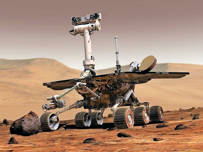
Figure 2: The Spirit rover on Mars. (Image credit: NASA/JPL)
Spirit operated from 2004 to 2010, about 20x longer than planned, after driving 7.73 km or about 13x farther than planned. Tragically, Spirit drove into a patch of soft dirt on May 1, 2009 and got itself stuck in the Martian soil. The AAA refused to send a tow truck. (“Sorry, JPL – Mars is well outside of our service area.”) Efforts to extricate the rover with fancy remote driving techniques failed, which effectively ended Spirit’s mission. Without mobility, the Spirit rover could not reposition its solar cells to point directly towards the sun and its batteries eventually gave out. Spirit froze to death in the Martian winter.
Opportunity fared much better. It operated from 2004 through 2018, an astounding 14 years, which is about 55x longer than the planned 92-day mission. Then, in June, 2018, a long-duration Martian dust storm enveloped Opportunity and robbed the rover of sunlight. Batteries depleted, Opportunity eventually ceased communicating. During the time it successfully operated on Mars’s surface, Opportunity traversed 45.16 km. Opportunity may yet revive, given enough sunlight. But as Sir Elton John sang in “Rocket Man,” Mars is “cold as hell.” Without power, Opportunity couldn’t keep itself or its batteries warm. That’s a bad thing.
Due to their meager computing capabilities, the Spirit and Opportunity rovers had severely limited autonomous driving ability. An operator would plan a day’s traverse and science activities and then would upload instructions to the rovers (after verifying them in a simulator). The two MER rovers then used their stereo imagers and navigation software to figure out the best and safest route to reach the designated destination while avoiding any obstacles identified by the stereo cameras.
Spirit’s and Opportunity’s navigation algorithm is called GESTALT (Grid-based Estimation of Surface Traversability Applied to Local Terrain). GESTALT is responsible for stereo vision control, traversability analysis, path selection, and driving. Here’s how the GESTALT autonomous driving system works:
- The autonavigation system takes left and right stereo images of the nearby terrain using the rovers’ body-mounted stereo hazard-avoidance cameras or the mast-mounted stereo navigation cameras.
- The GESTALT software looks for all pairs of pixels that show the same spot on the terrain. Distances from the stereo cameras to all such corresponding points, typically about 16000, are calculated using triangulation.
- The resulting points are modeled as a 3D geometric terrain grid.
- This 3D grid model is evaluated for safety using rover-wheelprint resolution. For each rover-sized grid patch, the points are fitted onto a plane and evaluated for rover traversability. Each patch is evaluated for steps, excessive tilt, and roughness.
- Objects are mathematically expanded by the radius of the rover so that the rover’s center will stay far enough away from the obstacle to keep the rover out of danger.
- GESTALT assembles all grid patches into a gridded traversability map that drapes across the terrain near the rover and includes previously imaged areas not currently visible to the cameras.
- A small number of possible paths are draped across the map and then each is evaluated for safety and by its ability to bring the rover to the goal.
- The rover then chooses the safest path that will take it closer to its goal. It then drives a short distance—no more than 75 cm at a time—along the selected path. (Remember, there’s no AAA towing service on Mars, so the rovers are exceptionally careful.)
- After each step, the navigation process repeats: take stereo images, generate the 3D terrain model, analyze, and move.
- The rover drives a few meters closer to the goal in short segments using the selected path and then repeats the process until it either reaches the goal, encounters an obstacle, or runs out of time.
Even this limited autonomy permitted longer daily drives than would have been possible by simply depending on step-by-step navigation commands sent from Earth.
Going Nuclear
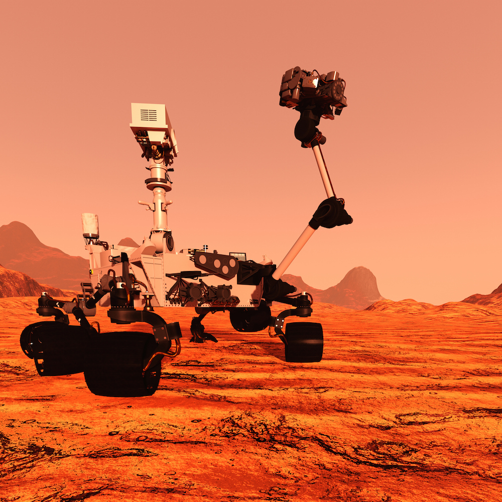
Solar power really didn’t permit the first three rovers much range. So the next rover to travel to Mars, Curiosity, runs on nuclear power in the form of a plutonium RTG (radioisotope thermoelectric generator) that generates more than 100 watts of electricity continuously, day or night, from nuclear fission. In addition, the RTG’s waste heat keeps Curiosity’s innards (batteries and electronics) warm. The mission parameters called for the RTG to last for at least two years. Curiosity was launched November 26, 2011 and landed on Mars on August 6, 2012. That was more than six years ago, and the rover’s RTG is still going strong. Typically, RTGs operate for decades (plutonium 238 has a half life of 87 years) and merely lose a bit of output power each year. Accordingly, the Curiosity RTG’s electrical output drops by a watt or two per year.
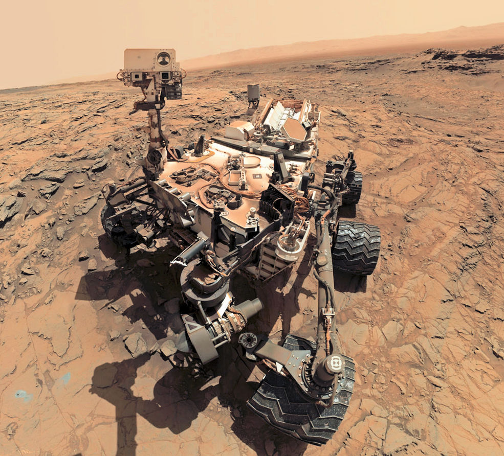
Figure 3: Curiosity rover on Mars. (Image credit: NASA/JPL)
An essentially inexhaustible power source effectively supercharged Curiosity’s drive train, which meant that the nuclear-powered rover could be expected to travel faster and farther and do more science than its predecessors. It needed a more powerful CPU to run the autonomous driving software.
Curiosity’s CPU is a newer RAD750 capable of operating at a 200MHz clock rate and delivering 400 MIPS. Like the RAD6000 CPU in Spirit and Opportunity, Curiosity’s RAD750 CPU is based on a PowerPC processor architecture. The “RAD” in each processor’s part number designation indicates that the CPUs are radiation hardened. Truly, as Sir Elton John sang, “Mars ain’t the kind of place to raise your kids.”
Curiosity landed on Mars on August 6, 2012 using an incredible landing sequence that combined a Rube Goldberg sequence of a heat-shield atmospheric entry, a supersonic parachute, retro rockets, and finally a sky crane that gently lowered the Curiosity rover to the Martian surface on a tether while the crane hovered overhead on rocket power. Then the sky crane cuts the rover loose and hurls itself away from the rover’s landing site to crash somewhere out of the way.
If you haven’t watched this landing sequence in NASA’s 5-minute film called “7 Minutes of Terror: The Challenges of Getting to Mars,” here it is:
Curiosity currently runs an improved version of GESTALT for autonomous navigation that runs 18x faster on the 400-MIPS RAD750 CPU versus the 22-MIPS RAD6000 CPU in the MER rovers.
NASA is planning to launch the Mars 2020 mission in, er, 2020. To keep mission costs and risks as low as possible, the Mars 2020 design is based on NASA’s successful Mars Science Laboratory mission architecture, which includes both the Curiosity rover and the now-proven sky crane landing system. However, the improved version of the Curiosity rover for the Mars 2020 mission includes some upgrades such as pimped wheels to better handle the rugged terrain. After more than six years, Curiosity’s aluminum wheels are developing extra holes, as can be seen in Figure 4.
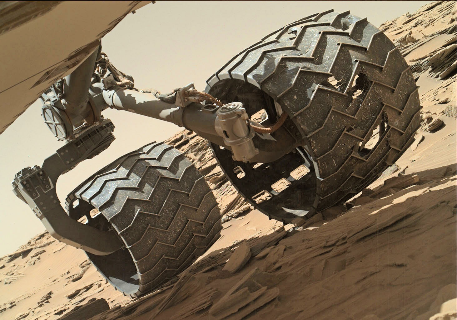
Figure 4: After more than six years of trundling over the Martian landscape, the Curiosity rover’s aluminum wheels are showing some wear. (Image credit: NASA/JPL)
The Mars 2020 rover’s autonomous driving system has also been pimped up using an FPGA coprocessor to accelerate many of the required algorithms. The Mars 2020 rover will still be running the GESTALT AutoNav algorithms, but when the mission launches, the new rover will be carrying an FPGA-based hardware accelerator called the Vision Compute Element (VCE, see Figure 5) that wasn’t present on the Curiosity rover.
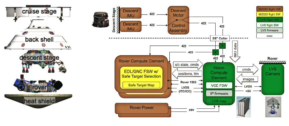
Figure 5: The Mars 2020 rover includes a new FPGA-based hardware accelerator in its Vision Compute Element (VCE) that will aid in landing navigation and autonomous driving on the Martian surface. (Image credit: NASA/JPL)
The VCE consists of three cards plugged into a Compact PCI backplane: a CPU card with the rover’s RAD750 processor, a Compute Element Power Conditioning Unit #1 or CEPCU1, and a Computer Vision Accelerator Card or CVAC. The CVAC is a new card developed for the Mars 2020 mission, and it’s an FPGA-based hardware accelerator for vision-based applications.
Early in the landing sequence, the CVAC accelerates tasks for the Lander Vision System (LVS), which reduce the initial positioning error prior to landing from as much as 3.2 km (based on inertial measurement alone) to 40 meters. Using an extra camera bolted externally to the rover’s body, the LVS finds landmarks by matching camera images against a stored map, in 10 seconds or less, while the spacecraft is descending from 4200 to 2000 meters above the planet’s surface. This computation gives the descent stage enough time to position the sky crane in a boulder-free area of the target landing zone.
As shown in Figure 5, the Mars 2020 descent stage and the rover share the VCE. When the descent stage is ready to lower the rover using the sky crane maneuver, the VCE’s connection to the descent stage is severed and the rover drops to the Martian surface. At that point, the VCE is repurposed for the GESTALT AutoNav driving algorithms.
The GESTALT algorithm employs a processing pipeline that consists of image acquisition, stereo analysis, visual odometry, traversability analysis, and path planning and execution. Image acquisition involves capturing, downsampling, transmission, and storage of images acquired from rover-mounted cameras. Stereo analysis decomposes into image rectification, filtering, and disparity processing. Visual odometry involves identification and tracking of features between images to estimate positional changes. Traversability analysis transforms stereo data into a map used by a path planner that approximates the relative safety of traversing a particular region. Path planning and execution uses the estimated position and traversability analysis to determine and command the rover’s next move towards the overall goal.
Not Your Daddy’s FPGA
The FPGAs on the CVAC are reconfigurable Xilinx Virtex-5QVs—which are space-grade, rad-hard FPGAs with 131,072 logic cells, 320 DSP slices, and 10.728 Mbits of BRAM—and a rad-tolerant, one-time-programmable Microsemi RTAX2000. The Virtex-5QV serves as a reprogrammable visual processor, and the RTAX2000 is permanently configured as a housekeeping chip. The RTAX2000 is also responsible for configuring and reconfiguring the Virtex-5QV FPGA.
Xilinx announced the Virtex-5QV FPGA way back in 2011. It’s hardened against single-event upsets, has total immunity to single-event latch-ups, can survive total ionizing doses of more than 1 Mrad(Si), and provides datapath protection from single-event transients. The BRAM blocks integrate error-detection and error-correction circuity. This is not your daddy’s Virtex-5 FPGA. (If you want to see JPL’s extensive test results for the Virtex-5QV FPGA, click here.)
The CVAC accelerates certain stereo-analysis and visual-odometry tasks using the Virtex-5QV FPGA. It implements the computationally expensive portions of the stereo analysis task, including image rectification, filtering, and disparity calculations. It also implements portions of the visual odometry task, including feature detection and matching. Feature detection uses corner detection, and feature matching uses a sum of absolute differences (SAD) algorithm applied over local regions between images in a sequence. The CPU performs the remaining steps in the pipeline.
The Virtex-5QV FPGA on the CVAC provides significant hardware acceleration for the GESTALT AutoNav algorithm tasks. Compared to a CPU-only implementation on a 20MHz RAD6000 CPU, stereo analysis runs at least 4800x faster for 256-pixel-wide images, while 512- and 1024-pixel-wide images that could not be processed at all by the CPU implementation are processed in less than a tenth of a second by the FPGA.
On the MER rovers, running on the 20MHz RAD6000 CPU, the visual odometry algorithm would take 160 seconds to estimate a relative pose change. On the Mars 2020 rover, with the visual odometry tasks split between the FPGA and the RAD750 CPU, the same algorithm requires 8.8 seconds. That’s an 18x improvement. However, the FPGA portion of the visual odometry algorithm – feature detection and mapping – takes 0.016 seconds for a 512-pixel-wide image, so the CPU is the limiting factor here.
The Curiosity rover has performed a ton of science in its 6+ years on Mars, and it will continue to do so, likely for years to come. When the Mars 2020 rover lands on the red planet in 2021, it will also perform a ton of science, and it will do so faster thanks to the FPGA that JPL has put into its driver’s seat.


Very interesting story. You should know that the genesis of the algorithm used by the Mars Rovers (as well as by Google Maps, the DARPA Grand Challenge, and many other autonomous devices) is SHAKEY the Robot, as developed at SRI from 1966-1972. With great help from Peter Hart, I led the effort that awarded SHAKEY with an IEEE Milestone in 2017. See http://www.ShakeyMilestone.com for lots of info. See in particular a portion of the dedication ceremony for this Milestone at http://goo.gl/jS6JWp wherein JPL’s Mars Curiosity Rover lead driver Matt Heverly describes how SHAKEY’s Shortest Path Algorithm is used by the Mars rovers to autonomously navigate on Mars – just as you describe in this story.
Thanks for the added perspective, Brian.