


We’ve talked a lot about security lately (a trend that’s not likely to diminish anytime soon). But much of the hard work of encryption and authentication and the like are done by software stacks – middleware that you can purchase or acquire as open source. Concerns about hacking also tend to focus on software vulnerabilities – the good news there being the patchability of software (as long as your system can be upgraded).
But what if you can attack hardware? What probably comes to mind are so-called side-channel attacks, where you listen to EMI transmissions and watch power fluctuations and somehow learn secrets from such studies. Amazing but true.
But what if you could execute an attack while a system is being designed or built? We look at three examples presented as papers at last year’s ICCAD. The focus in all three cases is figuring out that you’ve got a problem in your design – either a circuit or an actual thing.
Of course, the notion of “your” design is over-simplistic. If you’re in control of every aspect of a design, from soup to nuts, and if you’re using only your own code, and if you have no nefarious ulterior motives, then you’re probably OK. But big designs? Done with teams of designers? Some people talk about design closure as playing “whack-a-mole”; in this case, if you have a rogue designer, it’s more like “find the mole.” Or you might use open-source – or even proprietary – IP, in which case you’re no longer completely in control of the content of your design. Or your tools could get hacked.
So how do you know whether or not you’re OK? Let’s look at some different aspects that may not be obvious.
Do you know if a Trojan lurks in your FPGA design?
What if someone hid some bad behavior in your FPGA design? You might wonder what such a low-level design intruder could possibly accomplish; one example, given by Christian Krieg et al from UT Wien, makes a tweak to logic that decides whether a given instruction requires super-user status to execute. The attack is to allow a specific protected instruction to glide through without super-user status, thus creating a bypass around built-in security.
Of course, you figure that, if you’re doing all your simulations and achieving good coverage, then you’d discover such code, right? And if that doesn’t work, there are tools that can identify unused (or lightly used) code, so that should catch it, right?
Turns out, this story is more about how you can craft an attack – and it comes with a solution that FPGA makers would need to provide in order to ensure clean code.
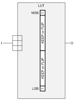
The way this attack is built leverages the look-up table (LUT) that forms the heart of the FPGA. For those of you less familiar with how FPGAs are built, logic is implemented by 4- or 5-input (typically) look-up tables that can implement any function of those inputs. The contents of the LUT are set when the device powers up and loads its program from non-volatile memory.
So this team plays a clever game with a LUT: they tie all inputs together (4 of them in their example). That means that, of all the functions that are theoretically possible from the LUT, the only ones that will ever execute are those where the inputs are 0000 or 1111. The other memory locations in the LUT can have pretty much any contents you want and they won’t affect the output. The functionality with a one-input LUT is limited to four functions: constant 0, constant 1, the input state, or the inverse of the input state.
“But,” you object, “FPGA tools start from high-level hardware languages and synthesize and optimize to get the LUT configurations.” Yes, that’s normally true. But you can get in there and do your own LUT-twiddling, even if that’s a less common occurrence. It’s like dropping into assembly within a C program. So that makes it possible to create explicit LUT logic.
This, presumably, would require a rogue designer, right? No, not if you could hack the design tools and have them automatically add rogue code. “Phsh, yeah, right!” would be a reasonable response to that. Except… this team did it. So it can be done. There’s then the challenge of replacing an unaltered EDA tool installation with the hacked version – they postulate this is doable through an internet-based attack.
The trick here is that, as generated, this added logic will do nothing to alter the normal behavior of the circuit. That special instruction that will bypass security? It doesn’t bypass it at this point; it will simulate with that instruction requiring super-user status. The other trick is that the added circuit is never placed into an actual design file, where it could be inspected. It’s added to the in-memory representation while the file is read by the hacked synthesis tool.
So now you’re wondering what good an inactive Trojan circuit might be. No good, as is. That’s the thing about Trojans: they may wait silently, doing nothing, until activated. And how to activate this particular Trojan? You need to hack another tool for this step.
Remember the LUT, with, in their example, 16 memory addresses (from 4 inputs), with only two of them (the MSB and LSB) used? That leaves 14 memory cells that you can put anything into. The team defined two 7-bit “flags” that were arbitrarily encoded in those cells. One is “Keep”; the other is “Flip.” The 14 bits are divided in two, with 7 bits encoding what should happen to the LSB and the other 7 indicating what should happen to the MSB upon activation.
When ready to create a bitstream, you again leverage a compromised backend tool. I’ll admit this also sounds unlikely, but, again, they’ve apparently done it. This tool has functionality that looks for these rogue cells, identified as:
- All inputs tied together (an unusual configuration, not likely to be found in a normal design created by standard EDA tools – therefore not likely to accidentally grab some legitimate logic by mistake)
- The 14 inner bits implement 2 codes, each being either “keep” or “flip” – this makes it even more unlikely that you’d accidentally trip over legitimate logic
Once the backend finds these blocks, it then changes (or not) the behavior of the MSB or LSB according to the specified instruction – either keep it as it is or flip the bit. At this point, the circuitry is now active. Any flipping is done only on the bitstream output; the in-memory representation is unaltered so as not to rouse any suspicions; the triggered Trojan would never be visible by the tools.
So just to summarize, the in-file versions have no extra LUT logic; the in-memory version has inactivated extra LUT logic, and the bitstream has activated LUT logic. Tricky.
Done crudely, security tools that identify unused or lightly used circuits, or that identify unused or redundant inputs might be able to detect the attack. It is possible, however, to work the malicious LUTs into the normal functionality (they show an example of how in the paper) so that the malicious logic will be used under normal circumstances, before being activated. In this manner, it can escape detection.
I have to admit, that last bit seems a bit of a stretch because it requires knowledge of the circuit design – something much harder for a hacked tool to do (as opposed to a rogue designer). But if you study a synthesis tool and look at what it generates, you might be able to identify a pattern that you can leverage in the tool. On the one hand, this sounds really hard. On the other hand, I’m not sure that it sounds
harder than deducing encryption keys from power signatures, to my naïve mind, anyway. So let’s keep rolling.
And where does all of this lead? To the only true solution that could catch anything like this: a formal equivalence checker between the final design and the bitstream. Simple, right? No, because the bitstreams use an unpublished format, so no one (well, no one except the FPGA maker) would be able to make such a tool. The conclusion is that FPGA makers should publish their bitstream formats so that such equivalence-checking tools can be built.
Upon further thinking, there would appear to be one more requirement for this hack to work. It relies upon changes occurring only in the in-memory version (to avoid discovery in a file). So, if you power up your tools, pull in your design, synthesize, and then generate a bitstream in one go, this could work. If you synthesize, then power the tools down (killing the in-memory model), and then bring them up again to generate the bitstream (without resynthesizing), then you’d be clean.
If the attack were to be “non-volatile” – that is, if it could maintain the malicious code even if the program is shut down, then that code would need to be saved in a file – say, the gate-level representation. Running an equivalence test between the gate-level version and the original design should find the change – unless the inactivated version could pass formal equivalence. I suppose you could play some trick saving the malicious code elsewhere, with the tools hacked enough to know to look for this secret file and stitch the code back in. Yet more work…
Even so, a tool might easily be written to identify low-level LUT definitions in the gate-level file. If no designer put them in manually, then that would be a red flag. So there are some potential ways of detecting this hack short of doing bitstream equivalence checking, but only in some circumstances. A bitstream check does make it failsafe, since the bitstream is the only version with the activated Trojan.
Detecting something a little bit off
The next story, by a team combining folks from the University of New Mexico, University of Florida, Florida Institute of Technology, and Intel, is about detecting subtle parametric changes that might indicate the presence of a hardware Trojan in a circuit. This is done by including a detection tool in the circuit itself; it’s not enough just to examine the design from outside.
The premise here is that, when activated, a hardware Trojan subtly changes circuit delays from what would be expected. Specifically, the activation detector would be an extra load not found in the simulation model, and the payload – which the detector activates – would change a logic path, also altering a path delay.
Their detection method focuses on structural analysis, not functional analysis, because it scales linearly with the size of the design, rather than exponentially. So it’s not about finding all the vectors that betray the Trojan; it’s finding the Trojan itself, or rather delays that betray the Trojan’s presence.
The high-level method is to analyze real delays and compare them to a golden simulation model. But there’s an obvious gotcha here: real circuits deviate from ideal based on all kinds of variations; very few real circuits will match a simulation model.
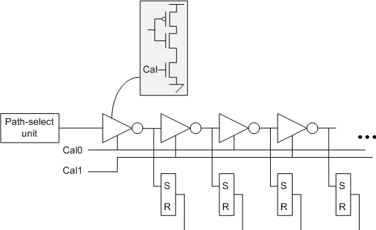
So the bulk of the team’s contribution is a system of eliminating variation as a confounding effect using what they call a time-to-digital converter (TDC). The converter itself consists of a string of “current-starved” inverters – the idea being that each inverter will narrow a pulse applied at the input. Stack a bunch of these in series and then apply a pulse at the beginning. As the pulse travels through each inverter, it will narrow, until, somewhere down the chain, it becomes too narrow to detect.
If you sample the output of each stage, you’ll see the pulse at the early stages and not at the later stages. The stage where the detection stops is a digital representation of the width of the pulse using “thermometer code.” (That is, a code that is all zeros on one end, all 1s on the other end, and what you measure is where the transition happens – like watching the mercury level in an old-school thermometer).
This detector can be affixed to some circuit (in their example, they use the outputs of AES encoders) to measure delays. The current starving is implemented by an extra transistor in each inverter; adjusting the gate of that transistor (this is an analog thing) will impact the speed of the inverter. This provides a calibration opportunity.
In fact, in their example, they used two calibration values: one for the even-numbered inverters and another for the odd-numbered ones. This allows them to calibrate rising and falling edges independently.
The technique goes roughly as follows: using an external voltage source, you run a test delay through the chain and sweep the calibration voltage up. The chain should speed up as current increases. The trick is to pick a delay value that’s the same for all circuits and for the golden simulation model. Let’s say you have a 20-bit chain; you can target an output value of 10 (that is, the bits before the 10th inverter register a pulse; the bits after the 10th inverter see no pulse).
By doing this on each individual chip to be tested, you calibrate out the sources of variation – whatever they are – and get the circuit to operate like the golden model. Once calibrated, you keep the calibration voltage at that normalizing level – which could be different for every chip – and then test the actual internal delays. Because you’ve normalized to the golden model, you can then detect subtle deviations from that model – thereby getting a better crack at detecting circuitry that has changed as compared to the model.
You sent what to the printer?
The third story involves hardware of a very different – and much more literal – sort. This attack is launched against a 3D printer to make potentially subtle changes to whatever is being built. The changes might be unnoticeable to the naked eye, but by subtly changing things like hole positioning or chamfers or other “minor” features, you can significantly weaken a structure without that weakness being evident to a casual observer. That’s obviously not good news for whoever is counting on the strength of the structure. Think airplane wings, for example.
This particular attack involves not just hacked tools, but also hacked printer firmware. And there’s a subtle distinction here. The attack doesn’t involve making the firmware mis-execute a given instruction. Rather, it envisions a hack where an existing instruction or set of instructions is modified – perhaps by changing parameters. The key is that the printer is correctly responding to the instructions it gets; it’s just that those instructions may deviate from the original design instructions.
Because this attack happens in the firmware, there’s no way to detect it in the design code (high- or low-level) because the code as fed to the printer is correct. So how to tell that something is amiss?
Here we come back to the notion of side channels, and, with 3D printers, one clear side channel is the sound made by all of the mechanisms as they respond to the instructions they receive. Of course, any analog parameter (EMI emissions, for example) can play a part – it may take a combination.
You then train a detector using a test set of inputs. This is supervised machine learning, and it creates a model that’s unique to a given printer. That model will tell you how the machine responds to varying instructions with varying parameters.
There’s one critical point to making this work, however, and I checked in with the team for clarification. This works only if the training is done before the firmware is compromised. That way you’re capturing the behavior of a clean system. This mechanism assumes either that the attack happens after the training, leaving the machine compromised for future designs, or, more specifically, that the attack is coordinated – the firmware change happens as the targeted system is being built.
It also occurs to me that side channel signatures can change over time – particularly audio ones – as parts wear. So the training might have to be renewed occasionally. How often would presumably be an empirical thing.
Now, when you run a build, you can:
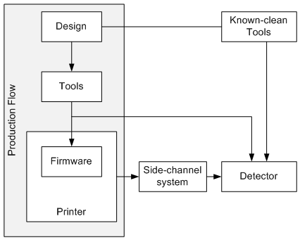
– Re-run the basic design-processing tools with a known-good tool set to make sure that there’s no disagreement between your newly-created code stream and the one being fed to the printer.
That takes care of compromised design tools.
– Compare the analog signature of each instruction to what would be expected of a clean printer. If there is a match, then the printer is likely clean. If something is off, then you get an alert, and you can examine further.
The first one can be done offline ahead of time (or after, I guess…). The second can happen in real time, if you have the processing power, or the signature can be captured for off-line analysis afterwards.
You can get more detail on any of these stories from the proceedings:
“Malicious LUT: A Stealthy FPGA Trojan Injected and Triggered by the Design Flow,” Krieg et al, ICCAD ’16, November 07 – 10, 2016, Austin, TX, USA
”On Detecting Delay Anomalies Introduced by Hardware Trojans,” Ismari et al, ICCAD ’16, November 07 – 10, 2016, Austin, TX, USA
“KCAD: Kinetic Cyber-Attack Detection Method for Cyber-Physical Additive Manufacturing Systems,” Chhetri et al, ICCAD ’16, November 07 – 10, 2016, Austin, TX, USA


What do you think of these and other hardware hacks and solutions?