


It’s time to take another look at the grid, yet another part of our world that is supposed to be getting smarter. And, for this update, there are two decidedly distinct aspects to address: the here-and-now – bits that can be used today, in particular for smart meters; and the yet-to-come – a look at some insights provided by Imec last month into their view of where things are going.
SoC me ASAP
The obvious main theme for what’s become available in the last few months has everything to do with SoCs and platforms for smart meters. Now, smart meters are, for some of us, old news. I’ve seen the battles, I’ve seen the chained-and-padlocked analog meters, and, well, all of that has disappeared from the headlines. Every house I’ve been in for the last several years has had a smart meter. So… we’re done with smart meters. Right?
And… if we’re done with smart meters, which have to last on the order of a decade and longer, then… who is going to use all the new chips coming out for smart meters? Haven’t they missed the boat until the next major upgrade?
Well, evidently things haven’t rolled out as completely as it looks from where I sit. I talked about this with Atmel, and they said that, contrary to my thinking, the US is only about 20% deployed. It got a good head of steam, but the bad economy slowed down the rollout, so there’s still lots to do.
Europe is even further behind, but there’s a mandate there to get 80% of homes equipped by 2020, so their plans are more aggressive. Asia (meaning, mostly, China, due to the obvious: their size) has a different approach going. They’re putting things out in two phases. The first, which is more or less done, is to get the basic meters out there without worrying about connecting them. These meters have expansion capabilities for the next phase. That second phase plugs communication modules into the existing meters, and it’s underway now.
So… so much for the rollout being a done deal. Guess there will be lots of new homes for these new smart meter solutions. Complete solutions and reference designs are the name of the game here. Each company is trying to build a case that they’re pretty much all that’s needed.
Atmel has split the smart meter into five chunks:
- the analog front end (AFE), which touches the actual power;
- metrology, which is where the bill collector gets his or her data;
- the ubiquitous application processor, where you can do everything that you haven’t decided to cast into hardware;
- communications protocols and encryption; and
- the communication physical layer.
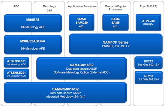
(Image courtesy Atmel)
The figure above contrasts various solutions they provide at different levels of integration. The first row is a more-or-less discrete solution to the problem, with only the AFE and metrology combined. The second row is for system houses that already have an approved metrology module that they don’t want to touch (because they’d need to go through approval again). So it integrates the other three columns.
The third row reflects the wishes of designers who want to keep their analog physical stuff away from their digital. So the digital bits are all combined, with separate power-line and communications PHY circuits. The last row would, you would think, combine everything into a paragon of efficient integrations, but… apparently that’s not what designers want. According to Atmel, they want to keep their communications PHY separate, as reflected in the integration shown in the final row.
“What do I do with the processor?” you might ask. And the answer would be, “Software, silly!” And what might that software do? This is where the creative bits can be. As with phones, the makers of these meters are trying to differentiate their systems so that they don’t all look alike. It can help with things like
- optimizing the power factor;
- optimizing efficiency;
- detecting wear-out, so that, for example, they can see ahead of time when a transformer is getting ready to fail; and
- identifying the power signatures of various appliances, both so that the homeowner can do a better job of managing his or her power and <cue Big Brother music> so that even the utility can help to manage the load by reaching in and tweaking with the appliances.
Of course, Atmel isn’t the only one in this game. Also in recent months, both Maxim and STMicroelectronics have announced smart meter solutions.
Maxim rolled out their Capistrano reference platform, whose block diagram follows.
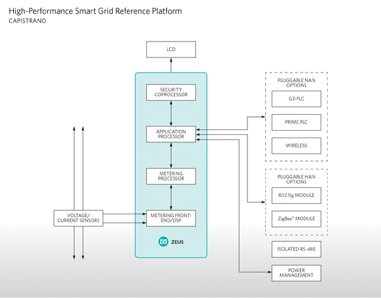
(Image courtesy Maxim)
The featured SoC here is their Zeus chip, which integrates four processors – a DSP for the AtoD stuff; a microcontroller for metering; an apps processor; and a security engine. They claim accuracy of 0.1% over an 8000:1 current range.
Meanwhile, STMicroelectronics launched their STCOMET SoC, which combines metrology and PLC communications. Now… if you, like I, have been hiding under a rock and think that PLC stands for “Programmable Logic Controller,” then come join me as we cross into the 21st century. This now stands for “Power Line Communication.” In other words, when radioing back to the Mother Utility, it doesn’t radio: it sends its signals on the actual power line.
This is less of a thing in the US, where wireless is common, but more common in Europe. In the US, we run about 7 – 11 homes for each transformer, but in Europe it can be hundreds, driven by a larger transformer. So they also put a data concentrator by the transformer, and the PLC module allows the homes to send their data to the concentrator.
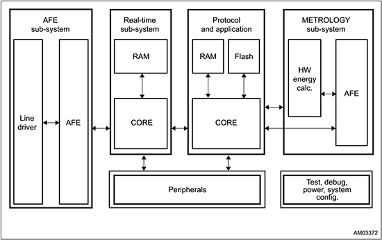
(Image courtesy STMicroelectronics)
The major STCOMET blocks start on the right, where the metrology block includes the connection to the power line for measurement purposes. Low-level processing is done here and passed to the Protocol and Application subsystem. Again, this is software, and it’s where the algorithms run. But it’s also where the top layer of the PLC protocol happens. The AFE subsystem on the left also connects to the line, but for communication purposes, not for measuring.
What’s coming?
OK, this is when we have to change the zoom factor by several orders of magnitude to look at the proverbial Big Picture. Imec has had a strong photo-voltaic operation for a while, and we’ve frequently seen their announcements as their silicon and organic operations make progress. (Imec is not shy when they think they have something to talk about.) But, aside from that, they’ve also been looking at other aspects of the grid.
Some of you may cringe a bit as they leverage the trending “Internet of” concept into the “Internet of Power.” The idea is that centralization of generation, storage, and distribution are giving way to “ubiquitous” de-centralized local instances. In addition, flow (power in this case; information in the IoT case) is moving from something smooth, controlled, and predictable to something much more highly variable. These traits mirror what’s happened to data communications as the internet has burgeoned. Hence the IoP thing.
Of particular note is the debate regarding where to generate power. In the US, we see the southwest as obvious for solar. In Europe, a similar approach would favor the south of France and other such relatively sunnier locations. (If you spin a globe around, you’ll find southern France to be at the same latitudes as Minneapolis, conspicuously lacking in herbes de Provence, and Portland, OR – slightly north of Portland, ME – with its highly-abbreviated Mediterranean-lite weather – you can thank the Gulf Stream for the radically different climates.)
Obviously, you can generate power more efficiently at mid-earth latitudes where the sun shines most directly. The problem is, you then have to get the power to where people want to use it, which means building lots of not-likely-to-be-popular transmission lines. And where they cross country boundaries, some governments may look somewhat askance at having to rely on a border crossing for their power. (Just ask Ukraine about natural gas…)
So the idea is that power should be generated close to consumption. That will require about 10% more generating capacity to make up for the lower efficiency, but it also results in 75% less transmission infrastructure, which will be pleasing to backyards everywhere.
But local generation also ratchets up the need for local storage to smooth out the disconnect between generation and consumption. So Imec has a couple of projects going to improve battery technology. One is focused on thin-film flexible batteries, which will have high power but “competitive” capacity; the other focuses on ceramic batteries, which feature high capacity but “competitive” power.
The fundamental structure they’re using involves:
- TiN as the current collectors;
- a Li4Ti5O12 anode, which exhibits minimal expansion, spinel structure (which carries both ions and electrons nicely), and 610 mAh/cm3 capacity;
- a LiMn2O4 cathode, featuring abundant, low-cost materials with low toxicity, spinel structure, and a capacity of 650 mAh/cm3 at 4 V; and
- an electrolyte, TBD, which must transport ions well and electrons not at all (the concept of a material that permits giant ions to pass but not teensy electrons does have me scratching my head); and it must have an appropriate electrochemical window, with good chemical stability.
This structure will be leveraged for thin film batteries by creating cylindrical posts, each cylinder being a small concentric battery. It will be used for ceramic batteries by pressing pellets together into a series of bipolar “stacks.” These are illustrated in the left and right figures below, respectively.
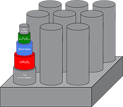
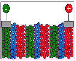
(Image courtesy Imec)
They see thin-film micro-storage emerging in the 2017 timeframe, right about the time that various ceramic demonstrators are available for evaluating different ceramic options. Solid-state flex thin-film batteries and full-on ceramic stacks are seen in the 2021 timeframe.
So this stuff is still a ways off, by their reckoning. By the time these find their way onto the grid (assuming everything happens as they envision), we’ll probably be on round two of upgrading smart meters in our homes. Well, except for the ones that still have padlocks on them.


What do you think about the SoCs and technology coming online for smart meters and grids?