


How do you know when your IC design is done? When can you declare verification victory? These are the questions that coverage is supposed to help with. When your verification has covered the entire circuit, for lack of a more precise way of articulating it, then you’re done. (At least, with that part of the verification plan…)
So how do you know what your coverage is? And how can different tools contribute to that metric? That was the original intent of the UCIS standard done by Accellera. Vice Chair Dennis Brophy described a situation where multiple players had to get together first to decide how to define coverage. The Big 3 EDA guys then all contributed technology, and, in 2012, UCIS 1.0 was released.
Did the standard… um… cover (sorry!) every possible element of coverage? No. It was primarily simulation-oriented. There’s apparently some facility for formal verification in there, but Mr. Brophy agreed that more probably could be done – especially after more experience with the current version. If enough stakeholders were to come forward with ideas for a 2.0 version, a follow-on effort is certainly possible, but that hasn’t happened – yet, anyway. So the UCIS team is dormant at the moment, even as Mr. Brophy assures us that many tools have taken up the 1.0 version.
Well, OneSpin (we’ve talked about their formal technology before) says that they have customers still struggling with coverage. Design verification product specialist Nicolae Tusinschi’s assessment is that, “Accellera’s UCIS 1.0 standard enables some forms of coverage interchange but there are no efforts to expand it and the working group is currently inactive.” They’ve announced a solution they’re calling PortableCoverage that, he says, “goes well beyond the scope of UCIS by focusing on formal coverage and results, including model-based mutation coverage and links back to the verification plan.” Let’s dig into this.
4 Coverage Cases
First, to be clear, OneSpin isn’t claiming to do everything that UCIS hasn’t done yet in the world of coverage. Staying within the realm that they control, they’re helping to improve formal coverage assessment and then to integrate coverage metrics between simulation and formal verification. They help both to view simulation and formal coverage together (via their Verification Coverage Integration, or VCI, app) and to refine the verification plan (via their Verification Planning Integration, or VPI, app).
Through their Quantify tool and Coverage Closure App (CCA), they create four coverage buckets:
- Elements that were covered and passed verification
- Elements that were covered and failed verification (i.e., need to fix some bugs)
- Uncovered elements – this indicates a need for better assertions
- Uncoverable elements – these are things that you can test until the cows come home, and you’ll never get a result, because it’s untestable.
To be clear, their coverage work focuses on formal coverage – how good are the assertions? The integration with simulation is not so much about what’s been covered by simulation vectors, but rather about letting the simulation tool know what might or might not be worth trying to test. In other words, those “uncoverable” tests can be updated into the verification plan so that no one wastes time trying to test the untestable.
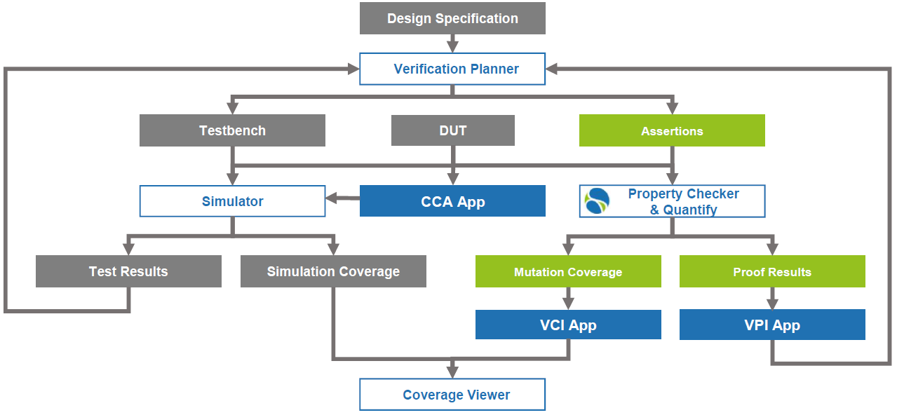
(Click to enlarge; image courtesy OneSpin)
Mutations as a Good Thing
The coverage calculation is done via mutations, which they claim is more accurate – and less overly optimistic – than existing methods; in particular, it’s different from how UCIS does it. Mutations aren’t new – tools already exist that mutate RTL and then check the impact. But OneSpin’s approach, which they say is patented, doesn’t work off of RTL. Instead, the mutations are made to a formal model. And those mutations are abstract and disconnected from any possible causes of the mutation.
There are four basic values to which a node can be mutated: 0, 1, X, and Z. You might think of those as stuck-at-1, etc. Other common fault models include bridging and opens. But those types of models are concerned with the physical cause of an issue. That means having some knowledge of the layout and possible nearby problems.
But at the PortableCoverage stage, you likely don’t have layout yet. That’s why it’s concerned only with the values that a node might have. If it’s a 1, is that because it’s stuck at 1 or perhaps because it’s bridged to a 1? Don’t know, don’t care. The question is, if mutated, will you know?
The other thing that this gets to is the distinction between verification and test. With verification, we’re trying to ensure that the design itself, if immaculately implemented on a silicon wafer, will work correctly. Test is concerned with ensuring that a manufactured device comports with the intent of the completed design (which, hopefully, was verified to behave as desired). So there’s an important distinction between what formal is doing and what test will eventually do. That said, the formal process identifies whether a mutated node can be tested – that is, that there is a controllable excitation path and an observable propagation path. Otherwise, you’ve got the proverbial tree falling in the forest with no one there to hear it. Or care.
It’s OK to Be Uncovered – Sometimes
What about those uncoverable nodes? What do those represent? There’s an old-school expectation – especially for mil/aero and other safety-critical designs – that every requirement have associated circuitry and that there be no circuitry that has no associated requirement. In other words, no Easter eggs, no fallow circuits. With that mindset, uncoverable logic would seem like dead code that must be removed.
But, in this more modern time, there are some legitimate reasons why you might have this dead code – and why you might want to leave it in place. The principal scenario is that of parameterized IP. You attach an IP block to your circuit, but that IP block – if bought off the shelf – is likely made for more than just you. So it has lots of parameters that let you set, oh, the number of lanes or the bandwidth or some other features.
Let’s say that there’s a feature – I’ll make one up – that allows a signature check on received data through a block, but you’re opting not to use that feature. So you set the signal that controls the feature to the value that disables the feature. Yes, if you’re using a code generator, then it might spit out code without that feature. But let’s say that’s not the case: the feature is there, but you disable it.
Well, now you’ve got all of that feature code that’s not doing anything. Will synthesis optimize it out? Maybe; maybe partly; maybe not. So does that mean you need to go in there and excise the now-dead circuitry? Probably not, for two reasons:
- You may not have access to the source code if it’s encrypted or if it’s a pre-compiled IP block.
- Going in and removing circuitry is like brain surgery: you may not know exactly what you might accidentally nick, causing strange symptoms and problems that you don’t want to waste time fixing.
So you simply establish, through the tools, that the circuits can’t be covered, and then, with VPI, you report that fact back to your verification plan so that you don’t waste simulation vectors on an impossible task.
Is this all what a putative UCIS 2.0 might have done? Who knows. Perhaps this will gain enough steam to move into standards territory. Or maybe this will remain a localized solution. I guess it depends on how big a problem is being solved here. OneSpin thinks it’s big enough to warrant a product; I guess it will hit standards territory if there are elements that different tools are doing differently, such that they need to harmonize them. It doesn’t feel like we’re there yet.
More info:


What do you think of OneSpin’s take on formal coverage?