

A lot of us think we’re faster FPGA designers than we really are.
We grab a few chunks of previous designs, munge them around a little bit, and bang out a couple extra modules for good measure. In what seems like no time at all, we mentally declare victory because we can upload our design to our development board and it kinda-sorta already does what we want.
We’re mostly partly almost done.
Except for finding and fixing a few little functional errors.
…which will require the remaining 95% of our allotted development time.
Functional debug starts off innocently enough. Our design basically works, and we just have to put it through its paces to be sure we didn’t miss anything important. (We did, of course.) We put together some vectors, or, no, wait, we could just use the hardware version of the design on the development board. Yeah, that’s it. Then we can use our normal stimulus and not mess with all the vector and simulator stuff. Bam! See? There’s a bug right there. Now, just what went wrong? Do we try to instrument the hardware, or should we load up the simulator to find out why it isn’t working?
When we start chasing down bugs in our design, we’ve always had two options available. We can set up some vectors and run our design in the simulator, or we can bump our design down into our development board and debug in hardware. In very broad terms, the simulator offers visibility, control, and fast iteration times (the time from finding a problem to cycling back and trying out a solution). The simulator also offers very slow execution – bordering on geologic time for large, complex designs.
Debugging on your development board solves the execution speed issue. Real hardware runs at real hardware speed. You can even connect up actual input devices and use them for stimulus. You can cover orders-of-magnitude more stimulus – allowing you to identify bugs much more quickly. The downside is that you don’t have the visibility and control that the simulator offers, so it’s much harder (and sometimes impossible) to locate the cause of the problem. Once you do, the cycle time to test out a fix is far longer – you have to recompile your design, re-synthesize, re-run place and route, and transfer your bitstream back to the development board before you’re ready to test again. In large designs, you may get a cycle only every day or so.
What we really need is the best of both worlds – the visibility, control, and fast iteration of the simulator combined with the blazing-fast execution speed of the development board. We also want to be able to mess around with the suspicious part of our design while the rest of the circuit stays stable and just works – at hardware speed.
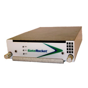
GateRocket has now come up with a solution that does just that.
We admit to being skeptical about previous versions of GateRocket’s hardware/software offering. Many designers watched the demo, read the articles and reviews, and then cocked their heads to one side with a confused expression – something like your dog does when you’re moving the treat box from one cabinet to another but not offering any to him. The early versions of the RocketDrive and RocketVision brought interesting but not clearly compelling benefits.
Now, however, GateRocket has added the “killer feature” that brings it all home. With their newly announced version 5.0, you can basically get the best of both worlds – the visibility, control, flexibility, and iteration time of the simulator combined with the raw speed of native FPGA hardware. If your head was tilted to the side from the previous versions, it will straighten right up now.
How does it work?
You basically interact with your design through your simulator interface. RocketVision supports HDL simulators from Mentor, Cadence, and Synospys. Behind the scenes, however, each block of your design is implemented in real hardware on the same FPGA fabric you’re targeting. The simulator is stitching together the blocks, but you’re getting hardware speed. When you get down to business with debugging, you can select some of the blocks to execute in software using the HDL models in the simulator. The rest of your design goes on in hardware, at hardware speeds.
The simulation blocks give you all of the capabilities you’d expect in the simulator, including the ability to make changes to the code and almost immediately see the results. This is where the system really shines. If you were running pure simulation, you’d still be waiting for the system to chug through all those vectors to get to the bug you just found. If you were running in hardware, you’d now have to re-synthesize, re-run place and route, and re-program your FPGA before you could see if your one-line HDL change worked. With GateRocket, however, you can zip right to the bug at hardware speeds, make your change in the HDL, and see the effects right away – without having to re-run synthesis and place and route.
In addition to facilitating high-speed find/debug/fix/test loops, RocketVision also enables you to do an automated compare of the hardware implementation with the expected results from the software implementation. This is a great way to catch all those places that you accidentally put the wrong pragma in the wrong place, allowing HDL simulation work perfectly while the hardware fails inexplicably.
A recent FPGA Journal survey (yep, the one you took) indicated that the process for identifying and fixing FPGAs by looping from the lab, where a bug is identified, back through simulation, synthesis, and place and route adds between 92 and 148 days to the FPGA design process. GateRocket claims they can reduce this process by 55% – (so maybe 60 days or so) by allowing the same bugs to be found and fixed during the simulation phase. By allowing the simulator to perform like the development board, many of us would be inclined to do more of our debug there, saving us some big time in the lab later on.
Our visions of fast design may not be illusions after all.


