Interest in FPGA reliability is not restricted to SEU environments. The US critical infrastructure, for example, often demands 24/7 operations and thus hi-reliability is frequently sought and very few, if any, of the infrastructure components are in SEU environments.
System failures are largely attributed to software-level errors such as unexpected input values, timing violations, and I/O shortfalls. To decrease the probability of system failure, many specialized, checking functions can be performed during runtime to make the software error-resilient. However, system performance suffers because the checking functions consume processor cycles that would otherwise be used for the mission software. In real-time situations this can create a designer’s dilemma: either forego a check so as to meet a deadline or run the risk of violating system safety if that check would have detected an error.
Our goal was to off-load these checking functions from the main processor onto another computing platform that would perform the checking functions concurrently with the main processor that executes the mission software. For this platform, we considered three possibilities: a microprocessor that would execute software versions of the checking functions; an ASIC (or non-reconfigurable FPGA); or a dynamically reconfigurable FPGA. The winner would be decided by which platform performed the checking functions fastest, but more importantly, which added the least burden to the system’s overall reliability.
A basic tenant of computer architecture is that hardware and software are logically equivalent. Migration of functionality from software to hardware yields speed benefits. In our earlier work [1], we developed tools (using Model-Technology’s VHDL simulation environment) that did more than describe the static FPGA hardware – it assisted in verifying that a virtual FPGA that is much larger than the physical FPGA could be created. This verification would have been impossible without explicit consideration of the intermediate reprogramming steps. Although exploiting a dynamically reconfigurable FPGA’s full versatility was, at first, somewhat daunting; the tools allowed us to find a hardware realization of the checking functions whose diversity would normally dictate a software solution. An orders-of-magnitude decrease in the execution times of the checking functions would result from realizing these functions in hardware. What follows, however, is the realization of the deciding factor: the reliability impact.
In digital logic, the unit of measuring complexity is gates. Gates are physical entities that occupy die space, consume power and take up a chip’s routing resources, so, in general, if the gate count is higher, then the reliability is lower. However, consider the notion of virtual gates: we see them but they are not there. These gates (note italics) are virtual in the same sense as computer virtual memory – where main memory is made to look larger than it physically is. When pages of main memory are not needed they are swapped out to disk and stored there until they are needed again. A dynamically reconfigurable FPGA’s cells implement gates that are connected to form a logical function; yet when this logical function is no longer needed and the cells can be reused by another logical function where do the gates of the previous function go? This is the key question in migrating complexity in a reliability-conscious way.
To answer this question, let us extrapolate from a widely accepted reliability-prediction method [2] that calculates the failure rate based on gate-count. We calculate the failure rate for the two cases: a conventional approach with fixed hardware logic where traditional gates are used, and the dynamically reconfigurable FPGA approach that uses gates. The ASIC (or non-reconfigurable FPGA) and microprocessor options for the checking functions fall under the fixed hardware logic case. As a brief side comment, the ASIC would not be considered a viable option in our application because if the system software changes (and software changes are not very uncommon), then the accompanying checks on the software would change too and thus dictate that we design, layout and produce a new ASIC. To accommodate these changes in a cost-conscience way, we would only consider the microprocessor or dynamically reconfigurable FPGA, however, for the reliability discussion below we include the ASIC.
For both the fixed hardware logic and the dynamically reconfigurable FPGA cases the failure rate, λ, is calculated by the formula:
λ= (C1π T + C2 πE) πQ πL Failures/106 Hours
Where:
1. C1 is the die complexity failure rate.
2. π T is the temperature factor.
3. C2 is the package complexity failure rate.
4. πE is the environmental factor.
5. πQ is the quality factor.
6. πL is the learning factor.
In the preceding calculations, the following values are constant: π T= 0.16, πE= 0.5, πQ= 3, and πL= 1. Regarding the constant learning factor for both cases, our dynamically reconfigurable FPGA is based on Atmel’s AT6000 series that the company advertises as mature technology (see http://www.atmel.com/products/FPGA/). As stated earlier, we carried out some early work with developing CAE tools that simulated the FPGA’s dynamic reconfiguration [1], and this also contributed to our climbing of the learning curve in using gates instead of gates.
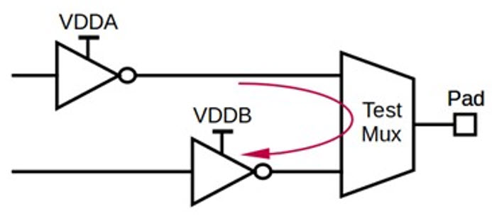
For the fixed hardware design, C1 is measured by counting the gates. Only when external storage (see Figure 1) is added can the FPGA implement usable gates; so initially C1 for the unprogrammed FPGA is based solely on the FPGA’s gate count that comes from the gates to implement the FPGA’s cells, on-chip memory to store the current program memory and the programming logic.

Figure 1: Basic Reconfigurable System
By adding external memory to store the various FPGA configurations, we increase the C1 factor of the reconfigurable design. However, the external memory permits us to migrate complexity from gates to gates. For external memory we turn to a masked-programmed ROM (MROM). Typical densities of MROMs are 16 Megabits per chip. In our modeling of the AT6000, three bytes program a cell, and it is assumed that a single gate is implemented per cell. Increases in the gate count of the target design imply a 3-byte increase in the MROM on a per gate basis. For example, 1 Mbits of MROM can be used to implement 41,600 gates. The C1 value for a MROM of this size is only 0.0052, while the C1 value for the equivalent number of hardware gates is 0.29 – a factor of 55 increase in complexity. With 16 Megabits of MROM, the FPGA can implement 666,666 gates.
For the fixed hardware solution, let us consider two sub cases. The first is a single package solution and the second is a two-package solution. The failure rate calculation for the reconfigurable approach includes three packages: the FPGA, the controller, and the MROM. The number of pins for the FPGA package is 224. The controller is assigned 1,000 gates and an initial package pin count of 36. Initially, the MROM of byte size 3 (for 1 gate) is assigned a 16-pin package. The number of address pins for the counter and the MROM are then increased with the size of the MROM needed to accommodate the gate count of the target design. Figure 2 shows the failure rates between a fixed hardware design and a reconfigurable design.

Figure 2: Number of Gates vs. Failure Rate
The horizontal axis is the number of logic gates required. For the fixed hardware case, this number is the same as counting the number of gates directly. For the FPGA, this is the number of gates implemented through dynamic reconfiguration where the unused gated are stored externally in the MROM. Initially, the failure rate for the unprogrammed FPGA is high due to its non-virtual gate count of 55,296. However, the complexity for each FPGA-implemented gate is placed into a significantly less complex 24-bit increment of MROM. As a result, the failure rate for the FPGA, counter and MROM grows only slightly as compared to the curves for the fixed hardware solutions. Comparing the failure rates of the reconfigurable and fixed designs, the sub case of the single package fixed-gate solution has greater failure rates when gate counts go above 130,000. At higher gate counts, the two-package sub case would probably occur, and as shown in Figure 2, its corresponding failure rate is dramatically greater than that of the reconfigurable design.
Modern microprocessors easily exceed the gate counts shown in Figure 2. Furthermore, the failure rates shown in Figure 2 do not include the memory that is required by software-based implementations of computer algorithms, and processor execution of the software is often possible only when the processor’s basic CPU functions are augmented by cache chips and memory management units – thus a multiple package solution would be expected.
For non-SEU environments, the maturing of dynamically reconfigurable FPGAs and the availability of tools to exploit their full versatility can bring the reliability of these devices “down to earth”. Storing virtual gates in rock-solid MROM migrates hardware complexity towards a reliability haven.
References:
[1] Kevin Kwiat and Warren Debany, “Reconfigurable Logic Modeling,” Integrated Systems Design, December 1996.
[2] MIL-HDBK-217, “Reliability Prediction of Electronic Equipment,” Revision F, Notice 2, February 1995.