

They say timing is everything, and when designing digital electronics, “they” are absolutely correct. Unless we can get the timing right on every path in our project, we’re going nowhere fast. Timing closure runs the gamut of our engineering tasks – from the inside of our FPGAs through our boards and out into the world.
With the proliferation of high-speed interfaces into common standards like DDR, PCI and others, even “normal” PCB design can involve complex timing issues, and resolving all of them at once can be a bit like squeezing a balloon. We have paths that need to meet minimum or maximum delay specifications, groups of paths that must be equal length, differential pairs that must be routed together, and phase alignment corrections that must be applied. And, all of these need to be handled during PCB routing – at the same time that we’re struggling with things like getting from point A to point B, minimizing the number of vias and layers, navigating our way out of complex BGA pin fields, and applying our sense of aesthetics to our work.
This challenge has been heard loud and clear by the folks who make PCB design software, and there has been a rash of announcements of new tool technology aimed at precisely this set of challenges. First, we’re going to look at the recent announcement by Cadence Design Systems – who have disclosed significant upgrades to their “Allegro” PCB design software. We chatted with Hemant Shah – Product Marketing Group Director, at Cadence about the recent upgrades.
Cadence comes out of the chute with a bold claim that TimingVision speeds board-level timing closure “up to 67%.” Wow, OK. We have no means to verify that, but let’s look at some of the opportunities for faster timing closure and see how Cadence is addressing them. First, we need to bring up the much-maligned topic of autorouting. If you design boards for a living, you probably don’t use autorouting, right? After all, you know what’s best for your design – way better than some dumb autorouter. Plus, autorouting is ugly, and you probably take pride in your work. You want people to look at your board and know that it was laid out by a pro. Finally, autorouters tend to get all mixed up when your design is heavily constrained, and you’d end up having to clean up the autorouter’s mess at the end anyway.
But, then, we’ve now got these thousand-plus-pin devices with tiny spacing landing on our boards, and nobody wants to spend the rest of their life helping hundreds of tiny traces escape from the labyrinthian confines of the BGA. What we need, and what Cadence has provided, is auto-assisted manual routing. That gives us the best of both worlds – we control the routing plan, and the tool does the detail work at our beck and call. Cadence calls this “auto-interactive” routing, and it can significantly reduce the workload of manually routing our designs. With auto-interactive routing we can select a group of nets and work on them together.
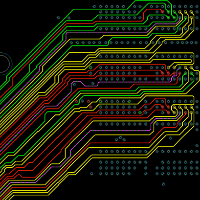
But, what if we’re working on something like a DDR3 or DDR4, or PCIe gen 3? Then we’ve got some pretty tricky constraints governing just how our routes must behave. Usually, we’re trying to get a group of routes to come out the same length, and/or with matched phase, and that can get us to the aforementioned balloon-squeezing issue with iterative design. Allegro TimingView has a built-in timing engine that develops smart delay and phase targets. Then, the editor displays the status of the nets we’re working on using a simple color-coded system: green is good, red is too short, and yellow is too long. The trace we’re working on is highlighted. We can push and shove and see the results in real time as we bring our routes into spec. TimingVision’s “heads up” display shows the progress right on the editing screen, which can save a lot of back-and-forth between the editing screen and the constraint manager.
What if we want some help with a particular interface that’s giving us trouble? In this case, Allegro TimingVision has what Cadence calls “Auto-interactive Delay Tuning” (AiDT), and “Auto-interactive Phase Tuning” (AiPT). We select the interface we want to work on, and the specific byte lane(s) we want to tune, and the autorouter works its magic – adjusting the lengths to meet the delay spec, and putting the proper phase corrections in for differential pairs that have phase constraints. For phase tuning, we can specify what kind of corrections we’d like applied – adding additional phase correction bumps or changing the approach to pads.
TimingVision offers two modes for both AiDT and AiPT – “DRC” mode and “Smart” mode. The “DRC Timing” mode doesn’t make a signal go “green” until it is in tolerance with all of the other signals in the match group. “Smart Timing” mode automatically identifies a “target” signal to fix and a min/max “goal” based on all the other signals in the interface. Each signal goes “green” or indicates progress based on its own min/max goal. Similarly, “DRC Phase” mode won’t make a net green until the whole thing meets the static phase rule. “Smart Phase” mode will make the “OK” parts of the net “green” and indicate only the rats of the net that need to be adjusted to meet the phase constraint.
TimingVision is designed to work in conjunction with Allegro’s power- and signal-integrity tools (from Cadence’s acquisition of Sigrity), to give a complete signal integrity solution for multi-gigabit serial interfaces.
All these new features obviously will save considerable time during the timing-closure phase of our PCB routing. Will it meet Cadence’s claim of “up to 67%”? Possibly. At least one customer quoted by Cadence claims to have saved 68% of the time they were previously spending tuning high-speed interfaces. Most of us probably don’t track our projects carefully enough to know how much we’re saving based on any given tool, but Cadence’s improvements will certainly take a lot of the stress and iteration out of what is normally a frustrating and somewhat open-ended part of our board design process.


