


This is the second part in our two-part series on the SADP version of double-patterning. I’d make some crack about your brains having recovered after Part 1, but realistically, despite all my overdramatic whining, that wasn’t that bad. That was the easy part.
In the first part, we looked at fundamental SADP concepts. (If you haven’t read it and this is new to you, I highly recommend…) But in the interest of focusing on the basics, I took some liberties (which I noted) that we now need to address. Now we need to figure out how to create an actual mask. This is where things start to look more evil.
You may reasonably ask, “Why are we doing this? My EDA tools will take care of this for me.” And the answer to that is, “Well, yes, you’re right – to an extent.” But depending on whom you’re working with as a foundry, you may have more (GlobalFoundries, e.g.) or less (TSMC, e.g.) control over the coloring of your masks. And some unexpected design rules accrue from this as well.
I’m not formally going to show how to color, nor am I going to go into detail on all the specific design rule implications. What I’ll do is go through a couple of examples and show how it all plays out. That should prep you for the kinds of things you might see in a real design.
We saw in Part 1 that sidewalls (or spacers) can help us to define features that we couldn’t mask directly because they’re too close together. And we saw that there are two “tones” to this: one where we define silicon features by letting the sidewalls protect them from etching and one where the sidewalls define the boundaries of the area to be etched for metal.
We’ll take these in order since that gives us the simplest case first. I should caution that, while I’ve been briefly schooled in how this works (an hour or two of expert discussion plus lots of rummaging around on the internet), I’ve gone solo on these examples. As with Part 1, it’s been extremely helpful to do them by hand, but it also means that I could have inadvertently missed some detail, as much as I’ve tried to double- and triple-check. Feel free to comment if you catch something like that.
Another caveat is that there’s more than one way to do this. I have found papers online showing steps that are different from what I will show. I have taken my guidance from Mentor’s David Abercrombie, who specifically noted that some examples from a research paper that I was originally following didn’t reflect what was actually happening at the 10-nm node. That’s not to say that the paper was wrong, but I do find the approach I’ve followed to be easier to grasp (for me, anyway).
So, while I’ve followed David’s guidance and used a more realistic process flow, bear in mind that there may be variants. As far as I can tell, my examples will be self-consistent, and they are useful in illustrating the challenges regardless of the final details of whatever process you end up using.
Getting Fin-nicky
Let’s go back to the first example we looked at last time, where we wanted to create three fin-looking features. We successfully showed how to do this, except that the final position of the fins was off. So let’s do it again and get them where we want them.
Our desired end result is shown in Figure 1. A quick color reminder: light gray is bulk silicon; light blue is an epitaxial layer from which our fins will be formed. Because the features are formed where the sidewall is, we need to create three sidewalls – one for each fin.
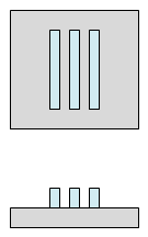
Figure 1. Final desired figure.
The problem is, you can’t create an odd number of sidewalls. Sidewalls form at the borders of mandrels, and a mandrel has both left and right sides, so you always get an even number. So we have to live with that; we’ll use the block mask later to get us back to three.
Figure 2 shows how we do that. Sidewalls are shown as light green. We will need two mandrels to give us these shapes. The dotted lines show where the underlying desired fins are; the rightmost sidewall is extra.
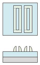
Figure 2. Where the sidewalls are needed
Now we need to get rid of the extra sidewall and define the top and bottom edges of the fins. We’ll use the block mask for this. Figure 3 illustrates this. The bottom and top of the blocking rectangle define the fin height; the overlap in the horizontal direction shows that there is some tolerance for overlay error in that direction.
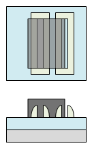
Figure 3. The block mask.
With the blocking photoresist in place, we can clear the extra sidewalls so that they correctly define the features we want and then remove the photoresist and transfer the pattern down, as shown in Figure 4.
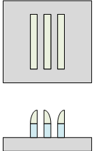
Figure 4. Sidewalls correctly reflecting the fin feature shape and position.
And, after removing the remaining sidewall material, we will have the correctly sized, spaced, and positioned fins.
It’s worth going back to the point made in Part 1 that SADP results in masks that don’t look like the features being laid down. That applies to this example, although it’s not a huge mental leap to get there. Figure 5 shows the mandrel mask and the blocking mask used to create the fins. (I’ve ignored whether it’s positive or negative resist. The tone might be reversed.) Mostly what makes this look somewhat off is that some aspects of the layout are missing. Those missing pieces are the ones that the sidewalls themselves create.
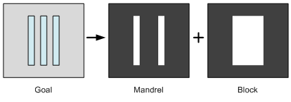
Figure 5. The mandrel and blocking masks used to create the three fins.
There’s one more very important thing we need to say about this example. What would happen if we wanted a fin that was just a little bit wider? That would mean we would need a sidewall that was a little bit wider. But you don’t get to dial up the width of a sidewall: its width is what it is.
This limits the kinds of features you can create this way enormously. In fact, you can create only lines that are a sidewall’s width (or double-width, as I hear tell). You cannot create arbitrary shapes because you cannot grow sidewalls that cover arbitrary shapes.
Creating a Dama-scene
Now that we’ve gotten the easy part behind us, we’re going to reverse the tone and work with metal. Instead of the sidewalls defining the shapes, the gaps between the sidewalls will define the shapes. So we are not bound by the limitation we just saw for silicon features.
I’m going to work a slightly more complicated example here. The reason is that most examples you see have lots of convenient simplifications. Things like having widths and gaps that are all magically the same as a sidewall width. In some cases that’s required, as we’ve seen, but in others it isn’t, and sometimes such simplistic examples hide some of the nuance.
So I’m going to work the feature shown in Figure 6*. Here gray is again silicon, brick-red is oxide, and the blue is metal. I’ve shown both horizontal views, with the view from the left rotated 90° as done early on in Part 1. This figure depicts what the final result should look like, with metal deposited into trenches in a typical damascene process. This is our goal. The critical dimensions are indicated with the double-headed arrows (that have degenerated into diamonds). These three spacings are the reason we have to resort to double-patterning here.
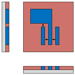
Figure 6. Metal features to be created using SADP.
I’m going to work through this more slowly because there are a couple of considerations along the way. Let’s start from the concept that the features will be defined by the spaces between sidewalls. The easiest way to depict this is simply to outline the features with sidewalls. We’ll need to tweak this in a moment, but for now, this is an easy way to start.
Figure 7 shows what that would look like. Note that this isn’t necessarily something we can build, but I’m working backwards from what we want to see how we can create it, so this is just a conceptual starting point. Again, light green is sidewall. I’ve used dots in the green and simple blocks in the horizontal views to reinforce that these aren’t necessarily real grown sidewalls.
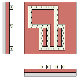
Figure 7. Sidewalls conceptually defining the features.
The trick now is to define a mandrel that will create this shape. Unlike the fin example above, the mandrel here may well consist of the actual features, but we can’t make a mandrel out of the whole thing because we can’t expose those features – that’s the whole reason we’re in this jam in the first place. So we have to get creative.
My sense is that there may be multiple ways to define mandrels that could give the same result; I’m going to take one straightforward approach, mindful that there may be others. In Figure 8, the light pink is a mandrel. The hashed green is the actual sidewall that this specific mandrel would create (shaped more like an actual sidewall in the horizontal views).
The mandrel consists of the actual large feature in the middle plus a leg coming down the left side to define the right edge of the left feature. This gives us actual sidewall in all the places we wanted it except for two places. We haven’t defined the rightmost feature yet and there’s a little bit of the “conceptual” sidewall that we didn’t manage to cover with actual sidewall.
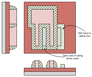
Figure 8. One mandrel can give us much of what we want, although not all.
That latter bit we won’t worry about; as you’ll see, we can take care of that with the block mask in a minute. So we won’t show that “conceptual” sidewall there anymore since it won’t be there.
But we still need to define the rightmost feature. So we’re going to need another mandrel to the right of it. While the first mandrel is mostly composed of actual feature, this second mandrel will be completely artificial; there will be no actual feature under it. So this can be referred to as a “dummy mandrel.” But notice that you need to have room to put it there; this will affect layout.
The dummy mandrel is shown in Figure 9. At the risk of getting too confusing, I have unhatched the sidewall we just laid down above. I want to focus on the right, where there is now a hatched pink mandrel. It’s hatched because it’s a dummy mandrel. The sidewall that it “creates” is also shown hatched here to distinguish it from the sidewall we already laid down with the first mandrel.
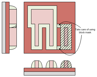
Figure 9. A dummy mandrel lets us define the remaining feature.
Once again, there are a couple of pieces of the original “conceptual” sidewall that we haven’t managed to create. They define the top and bottom of the rightmost feature. We’ll need to use the block mask to handle that as well.
With our mandrels in place and a plan to create all the sidewalls, we can now figure out how to block it out. Figure 10 shows the block mask. How do we come up with this? It needs to:
- Define certain feature edges.
- Trim away unwanted sidewall.
- Cover all the areas that won’t have any metal.
I’ve shown it as overlapping the sidewalls slightly where it’s not defining a feature edge. This is to reinforce the fact that, in these places, it’s the sidewall that defines the feature, meaning the mask registration is less critical, and it can overlap the sidewalls. Frankly, it’s this relaxed characteristic of the second mask that makes SADP attractive as compared to LELE, which is so sensitive to overlay errors.
Notice also where those three bits that we didn’t manage to cover with sidewall are now blocked out by the block mask (light gray arrows and text).
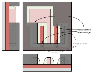
Figure 10. The block mask trims away excess features.
After exposing with this mask, but with the photoresist still on, we can clear away the mandrels (except for the parts that are covered by photoresist). This is shown in Figure 11; the underlying oxide is now exposed.
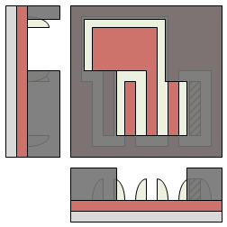
Figure 11. Mandrels have been removed, exposing the oxide underneath.
And now we can transfer our pattern through the oxide to create trenches for the metal. Figure 12 shows the result after the oxide etch. The left horizontal view gets a bit messy because you’re looking through a few layers and I’ve tried to capture that… sorta.
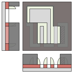
Figure 12. After etching the oxide to create the trenches.
Now we can clear away all the resist and sidewall material (we already cleared the mandrels before). This leaves nothing but trenches, as shown in Figure 13.
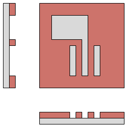
Figure 13. Trenches etched, ready for metal.
And then we lay in the metal, and… voilà! Just what the doctor ordered (Figure 14).
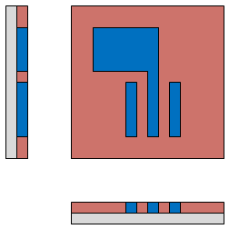
Figure 14. Metal in place looks like the original that we were aiming for.
To be clear, this wasn’t an obvious exercise to me. I totally had to think through where the mandrels would be, and I got the block mask wrong a couple of times. It took a fair bit of futzing before I was convinced that I had it right. (Which I hope I do.) It’s one of those things where, if it doesn’t seem obvious, it’s because it’s not obvious. (At least to me… without work…) I cannot imagine what the poor EDA dudes working on automated algorithms for this must be up against!
Let’s look again at the masks we get from this (Figure 15). This is less obvious than our fin example above. Again, the sidewalls fill in the missing bits. But the masks also have extra bits (the dummy mandrel) that don’t appear in the final pattern.
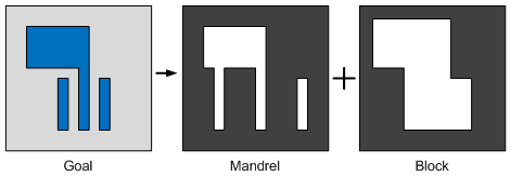
Figure 15. The mandrel and block masks required to get the features we wanted. Not obvious…
There’s one more note here that relates to the caution I provided with the fins. In that case, our features were limited by the sidewall dimensions. In this case, that doesn’t limit us – but the gaps between features are affected.
Let’s assume we wanted to move the rightmost feature a bit more to the right. Now we have a problem: that spacing that we had was a sidewall’s width; now it will be a tad bigger than the width of a sidewall. This is one of those situations where most examples have everything as a sidewall width, whether it needs to be or not, and they never make note of the fact that, for some features, this isn’t by accident; it’s important, people! If we try to move that feature to the right, we run into trouble: we have no way to create that gap because it’s too wide for a sidewall.
This hints at some of the funny design rules that you run into. In fact, there’s a “forbidden zone” in the spacing. Either your spacing is a sidewall’s width (perhaps double-sidewall?) or it has to be far enough away to use a feature on the mandrel mask (not a dummy mandrel; in fact, not really a mandrel, since sidewalls won’t be involved). There’s no in-between allowed because there’s no real way to pattern the in-between cases. This is illustrated below in Figure 16.
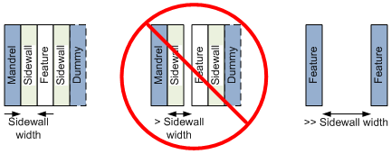
Figure 16. Spacing restrictions due to the use of sidewalls to create the spaces.
If the spacing is a sidewall’s width, then you can create these two features with a mandrel and a dummy mandrel. If they’re far enough apart, then you can simply pattern the features. In between… you’re out of luck.
So there you have it. A tour of SADP. I will honestly say that, after going through these examples, my head feels like a block of lead. I feel like I’ve met evil and stared into its beady eyes. I’m not complaining or trying to get sympathy or attention; just owning up to the fact that this took some mental gymnastics on my part. Granted, I’m not a practitioner, so I was starting from behind.
But I guess my point is that this takes some wrapping your head around. You won’t have to do all of this by hand, but you may well run into a situation where, for example, your design comes back with DRC errors because a dummy mandrel has violated some design rule. First of all, many such errors will be challenging for EDA guys to present. But even once they do, if you’re not aware of what’s going on, it will make absolutely no sense whatsoever.
So I hope that this has been a useful exercise for you. As for me, I need a drink… To celebrate good triumphing over evil. For the moment, anyway.
*It just occurs to me… this feature looks like a typical Santa Cruz neighborhood layout anywhere within a mile or two of the beach. Originally one property, subdivided with two tiny houses up front and a flag lot in the back. Why have one house when three will do? Oh, of course, each one of those mini-houses is worth $700K and up. Right?


We’ve worked out how to create SADP masks. Or at least I’ve tried to. And, by the way, there’s a quad-patterning version of this coming too. What’s your reaction to it?