

We don’t often stray from the realm of the electric in this space. But our electrical phenomena take place in physical materials, and we house them in other physical materials, and, as we ascend from the domain of the quantum, at some point, the physical features get large enough to where we can not only imagine them, but actually see them.
And, with increasing attempts to use elaborate packaging schemes to achieve more than Moore legislated, we keep getting dragged back out of the electrical and into the mechanical.
We did that earlier this year with a look at a specialized tool for characterizing various standard packaging combinations, but that left open the general case where we’re building custom packaging. And, once you go custom, it more or less doesn’t matter whether you’re packaging an IC, a combination of ICs, mounting packages on a PC board, or housing PC boards on a chassis in a box.
If you’re trying to get rid of heat, the IC package has to be optimized, the PC board has to be optimized, and the chassis and box have to be optimized. And the general tool for doing that will be the same since it’s largely a matter of finite element analysis and moving little bits of virtual heat around in a computer to simulate where the heat is going and how fast.
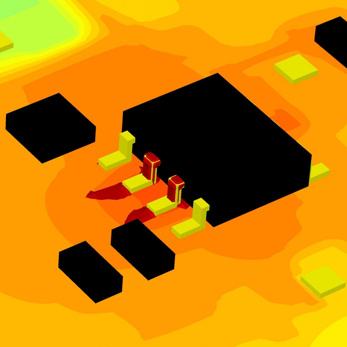
Of course, there’s nothing new about that. We’ve all seen those pretty colored images showing the hot spots and the cool spots. We’ve seen those in our own dice, except showing current flow instead of heat flow.
But one increasing trend in tools is to do more than just tell you how things are. More and more, tools are telling why things are. And, even better, how to change how things are. Those used to be completely left to the engineer, which was fine when dealing with small, tractable problems. But complexity today (not to mention schedule expectations) is such that you can take all the help you can get.
So Mentor’s FloTHERM tool is taking a step in that direction. Note that this isn’t the FloTHERM-IC of prior mention; this is the full-blown thermal simulation tool. In addition to pointing out where things are hot and where they’re not, they will now alert you to bottlenecks and shortcuts using the same kind of false-color graphics, but with different interpretations.
It’s funny how, in their presentation, Mentor presents analogies for the concepts of bottleneck and shortcut. In fact, the names themselves contain the analogies. So, from a heat standpoint, a bottleneck is simply an area where the flow of heat becomes constricted as it goes from point A to point B. And a shortcut is an opportunity that the tool sees to bypass a circuitous heat path; such a roundabout trek is likely due to some obstruction that, if eliminated, would result in more direct heat flow.
The math behind it is actually rather straightforward, even accessible to an electrical guy, to a digital guy, and to a marketing guy. [The author shamefacedly pleads guilty to all charges.] There are two similar-looking equations, one used for bottlenecks, one for shortcuts. And they involve: [are you sitting down?] trig functions. I know, at that point I usually surrender, fold my hand, capitulate, go find something easier to do like go see if Schrödinger’s cat is still alive (I keep trying to sneak up fast enough it catch it in the act of dying… or… the act of not dying).
But wait, don’t go yet, it’s not that bad. As used here, think of them as simply fuzzy 1s and 0s. It’s just that, instead of being only 1 or 0, they can also be somewhere in between.
Here’s the deal: when looking for bottlenecks, at each point they evaluate the “bottleneckiness” of that point relative to the worst bottleneck point as follows:
Bn/Bn(max) = |Flux| * |Gradient| * cosθ
where θ is the angle between the flow at that point and at a neighboring point. (And Bn stands for Bottle-neck). Now, since flux=flow=current and gradient=potential, then flux*gradient is basically resistance. So what’s happening here is that the resistance at the point is being “adjusted” by multiplying by some number between 1 and 0 according to its direction relative to its neighbor. If it’s going in the same direction, the cosine factor gives it full value; if it’s going off at right angles, it becomes zero.
In other words, if there’s lots of flow in some part of the material (silicon, package, PCB, whatever) compared to other parts, and, if it’s all going in the same direction, then it’s probably a bottleneck.
If there’s lots of flow and it’s all going off in different directions, well, then you have something else. In fact, what you have then is an indication of an obstruction: for some reason the heat can’t flow straight. This would suggest that, if the obstruction were removed, a shortcut could be created. And how do we reverse the bottleneck math to get higher numbers at right angles instead of straight? Of course: swap out cosine for sine.
Sc/Sc(max) = |Flux| * |Gradient| * sinθ
This gives you the “shortcuttiness” of the point relative to others. (Where Sc stands for Short-cut.)
This also says that the best situation is uniform current all in the same direction. Then the bottleneck calculation comes up the same for all points – that is, no point is any worse than any other. And the shortcut calculation goes to zero because of the sine.
Of course… that last bit about the shortcut calculation gets interesting since that means the numerator has to be 0. And if every point is equally shortcutty to every other point, then the worst case one is also zero. And that’s in the denominator. So… are you likely to find a singularity in your material? Only in the most ideal case. Which probably isn’t the one you’re dealing with. So don’t worry about it; you’re not in danger of having your circuit sucked into a black hole. (At least as long as you’re not near the Large Hadron Collider.)
There, that wasn’t so hard, was it? Well, perhaps it was: as simple as this might sound, it’s apparently novel and non-obvious – meaning that patents have been applied for. And it’s not been done before, according to Mentor.
As illustration, Mentor shows the tool being used first to determine that a solder pad would be beneficial under a packaged chip to help remove heat from the chip (and we’re not talking sophisticated here: 44-pin SOIC on a six-layer PCB). Doing so reduced the thermal resistance by nearly 24%. Then they saw the opportunity for another shortcut, adding thermal vias through the PCB board to reduce the resistance a further 16% from its value with just the solder pad. And, from there, they found that the plastic in the package between the die and the solder pad was a bottleneck, and so they decided to drop the die structure within the package so that it would meet the solder pad. This provided almost a 55% reduction over the prior configuration.
That’s for a simple package. Where this could get particularly interesting is in the analysis of the complex configurations being contemplated for 3D packaging and such integrated schemes as System on Package/Panel (SoP). We’re trying to take more and more heat-generating items, pack them into less and less space, and hold them there with plastics and other more-or-less non-thermally-conducting materials. So now we have to figure out how to market these devices as something other than really cool (or hot) exploding 4th of July toys.
And, simple examples like the above notwithstanding, it’s not just a matter of shifting things around and shoving in bits of metal shrapnel here and there to coax out the heat. Much more elaborate schemes like micro-channel cooling are under investigation, and the math to calculate the heat moving through moving fluids gets tricky.
Which is why we marketing types (even if engineers) leave the math to the real engineers, and the digital types leave it to the analog types, and the electrical types ultimately defer to the mechanical types to get it right.
There’s only so much trig we can take in one day.
More info: Mentor FloTHERM


